This lab is an introduction to Fundamental OpenGL Functions
After the lab lecture, you have one week to:
Before you begin this seminar, create a new template project like you did in the first lab - like the first one before you added triangle code. You will complete the project by following the instructions in this lab's notes instead.
OpenGL is an operating system and hardware platform independent graphics library designed to be easily portable yet rapidly executable. Unlike Direct3D, which is only available on PC, Xbox and Windows Mobile OS, OpenGL is available on a wide variety of hardware platforms and operating systems including Unix/X11 (Linux, BSD), Mac OS X, and Microsoft Windows 98 to Windows 10.
On the desktop, OpenGL stayed relevant through a robust extension mechanism and with major releases throughout the 2000s. In February 2016, OpenGL received a massive update called Vulkan , which has features comparable to Direct3D 12. The first games for Vulkan appeared soon after. A few notable recent games with Vulkan support include Doom Eternal, Half Life: Alyx, Crisis Remastered (1, 2, and 3) and the 2024 Game of the Year: Baldur's Gate 3. Vulkan will run on hardware that can support OpenGL ES 3.1 or OpenGL 4, including Switch, Android since v9.0 and all recent Windows desktop. Apple does not support Vulkan directly, preferring their own Metal API, but Khronos provides a compatibility layer called MoltenVK.
An embedded version, OpenGL ES, is available on many hand
held devices including iPhone OS and Android OS devices. Javascript versions
of OpenGL ES 2.0 and 3.0 are an official part of the HTML 5
specification and are available as WebGL 1.0 (Feb. 2011) and WebGL 2.0 (Apr. 2017). As of January 2021, WebGL2 support is available on nearly 92.8% of the browser market, and WebGL 1 is at 95.2%.
getContext() command by providing an optional Context
Attributes argument. The WebGL Specification
provides a full list of
context attributes, their defaults, their purpose, and an example of use.
gl at the top:
let gl; //Generic variable, intended to hold WebGL2 RC object
The Rendering Context object is acquired with the getContext() function built
into HTML5 canvases. This function may also provide access to other types of renderers.
  //find canvas by id name
  let canvas = document.getElementById( /* your canvas element's id goes here */ );

  //get webgl RC and do some minimal error checking
  gl = canvas.getContext('webgl2', // all defaults attributes in spec.
      {
          'alpha': true,
          'depth': true,
          'stencil': false,
          'antialias': true,
          'premultipliedAlpha': false,
          'powerPreference': "default",
          'failIfMajorPerformanceCaveat': true,
          'desynchronized': false
      }
  );

  if (!gl)
  {
    //This is friendlier than an alert dialog like we use in the template
    canvas.parentNode.replaceChild(
        document.createTextNode("Cannot get WebGL2 Rendering Context"),
        canvas
      );
    return;
  }
Once you have a rendering context, all your interactions with WebGL will be
through the object. This means that if your rendering context object is called
gl all WebGL2 calls will begin gl.. Many WebGL2
constants are
also defined as members of the rendering context object. For example, in this
lab you will see:
                   Functions                       Related Constants
                   ===============                 ======================
Data Management    gl.createBuffer()
                   gl.bindBuffer()
                   gl.bufferData()                 gl.STATIC_DRAW
                                                   gl.DYNAMIC_DRAW
                                                   gl.STREAM_DRAW
                                                   gl.ARRAY_BUFFER

Shader Connection Management
                   gl.createVertexArray()
                   gl.bindVertexArray()
                   gl.getAttribLocation()
                   gl.enableVertexAttribArray()
                   gl.vertexAttribPointer()
                   gl.getUniformLocation()
                   gl.uniform*()

Built-in Settings
                   gl.clearColor()
                   gl.clearDepth()
                   gl.cullFace()                   gl.FRONT
                                                   gl.BACK
                                                   gl.FRONT_AND_BACK

                   gl.frontFace()                  gl.CW
                                                   gl.CCW

                   gl.enable()                     gl.CULL_FACE
                                                   gl.DEPTH_TEST
                                                   gl.POINT_SMOOTH


Draw               gl.clear()                      gl.COLOR_BUFFER_BIT
                                                   gl.DEPTH_BUFFER_BIT

                   gl.drawArrays()                 gl.LINES
                                                   gl.LINE_LOOP
                                                   gl.LINE_STRIP
                                                   gl.TRIANGLES
                                                   gl.TRIANGLE_STRIP
                                                   gl.TRIANGLE_FAN
                                                   gl.POINTS


General
                                                   gl.FLOAT
                                                   gl.UNSIGNED_BYTE
                                                   gl.TRUE
                                                   gl.FALSE
For a full list see the section on WebGL2 Context in the WebGL2 Specifications, or check the Mozilla Developer's Page on WebGLRenderingContext.
Before you can do any drawing you need to tell WebGL what to do with the things you tell it to draw. You do this with shader programs written a language called GLSL. Shader programs consist of a minimum of two parts: a vertex shader and a fragment shader.
You may also have heard of two other shader types: geometry shaders, tesselation shaders, and compute shaders. Geometry shaders were introduced in OpenGL 3.2 with GLSL 1.50, tesselation shaders were introduced in OpenGL 4.0 with GLSL 4.00 and compute shaders were introduced in OpenGL 4.3 with GLSL 4.30. These extra shader types are optional in all versions of OpenGL.
WebGL1 supported GLSL 1.0 ES, which is based on GLSL 1.20 and had only the two basic shader types. WebGL2 allows us to use OpenGL Shading Language 3.00 ES (GLSL 3.00 ES) as its shader programming language, but can still use the old WebGL version if necessary. GLSL 3.00 ES is a modified version of GLSL 3.30, so WebGL2 supports geometry shaders if you want them.
A WebGL shader with no version code will default to GLSL 1.00 ES which is very different and far less powerful than
GLSL 3.00 ES. To explicitly select a shader language, the very first characters must state the version. No spaces or
new lines should come first. As a convenience, the textbook's initShaders()
functions strip leading
whitespace from shader programs so you can use tidy formatting in HTML and still compile your shader. All parts of a
shader program must use the same version.
#version 300 es
You will send lists of vertex information into a vertex shader. This
information comes in through variables labelled with the in
modifier. This information represents attributes that can change
from one vertex to the next such as colour and position. In older GLSL
programs, vertex shader inputs are marked attribute. This term is still used in other places.
You can also set values before you draw with a shader that will stay constant while the shader is running. This is
done by setting variables labelled with the uniform modifier. You will see more
about this later.
When we are done using attributes and uniforms to calculate properties for a vertex, we pass the
results along to the fragment shader through outputs labelled with the
out modifier. The vertex shader outputs for the
vertices in the same primitive will be interpolated across the primitive
- if they aren't all the same, their values will vary from fragment to fragment. In older GLSL programs, vertex
shader outputs are are marked
varying.
Below is our first vertex shader. Replace the vertex-shader in your template with this vertex shader code:
        #version 300 es

in  vec2 vPosition; //receives incoming vertex positions

out vec4 color;    //passes the colour of this vertex to the fragment shader

void main()
{
  //Add z and w coordinates to the incoming position and pass it on.
  gl_Position = vec4(vPosition, 0.0, 1.0);

  //Colour every vertex red
  color = vec4(1.0, 0.0, 0.0, 1.0); //colour channels are red, green, blue and alpha
}
This vertex shader only has one attribute and no uniforms. The attribute represents a 2D coordinate for
the vertex and has data type vec2 - a 2 component vector which has a base type of
float. Vertices can be moved around in space, coloured, and lit by
the vertex shader. You will explore many of these things later. For now, our
vertex program will only provide a colour for the vertex. This colour is hard
coded and will be the same for all vertices. You will learn how to change this
colour with a uniform or an attribute later in this lab.
Our first vertex shader uses two outputs as well. You can see the
declaration for a 4 component vector, vec4, for colour, and we use
the built-in output gl_Position, which is also a vec4. GLSL does not perform any type
coercion,
which is why the shader adds two more components to vPosition when
it is assigned to gl_Position.
All vertex shaders have a second built-in output, gl_PointSize which controls
the size of points. Its
value controls the point's width in pixels.
The fragment shader gets data that is blended from each vertex that makes up the primitive being drawn. This could be a position somewhere between each vertex, a texture lookup coordinate, or a blended colour. For now, our shader will ignore the built-in inputs and simply copy the incoming colour to the screen.
Replace the fragment shader in your template with this fragment shader code:
        #version 300 es
precision mediump float;

in vec4 color;  //The blended fragment colour from the vertex shader.
                //Names of inputs to a fragment shader must match
                //an output from the vertex shader.

out vec4 fragColor;

void main()
{
    fragColor = color;
}
This fragment has one input for the interpolated colour. It is important that names and data types for the inputs you create in a fragment shader match the name and data type of an output you create in the vertex shader.
This shader also declares an output. There is no built in color output from fragment shaders. Instead, the fragment
shader must declare at least one output. Typically there is only one output from a fragment shader, and it goes draw
buffer 0 - which will usually be your canvas. If there are more outputs, they will go to other draw buffers which
must be specified with location numbers. These outputs may be grayscale, declared with float or
uint.
Fragment shaders have three built-in inputs:
highp vec4 gl_FragCoord the fragment's position in the frame buffer (often
the canvas)
bool gl_FrontFacing - indicates if the front (true) or back
(false) is facing the viewer
mediump vec2 gl_PointCoord - used to create
shaped, varicolored, or textured points. [0.0, 1.0] for each component.
gl_FragDepth - allows the fragment shader to override the default depth of a
fragment - the z value
of gl_FragCoord.
initShaders() functions that can do all this for
you. I strongly suggest
that you use one. If you are lucky, your lab instructor will explain how to use all three.
You should call initShaders() from within your init() function, and use the result as the active
shader something like this:
      // Load and compile shaders, then use the resulting shader program
    let program = initShaders(gl, "vertex-shader", "fragment-shader" );
    gl.useProgram( program );
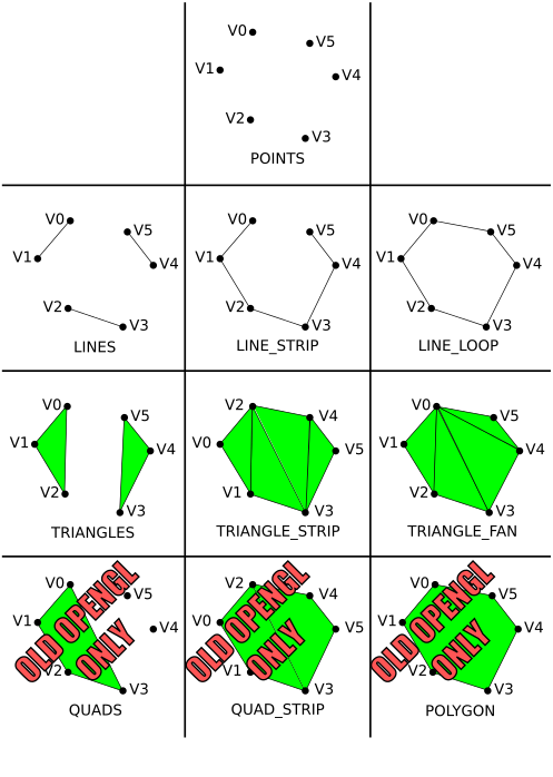
Your graphics hardware has limited ability to represent geometry. Most hardware only knows how to render triangle primitives. Everything else is built up using triangles. Older versions of OpenGL included some other shapes that might have been supported by some specialized hardware, such as convex polygons and quadrilaterals, but that support has been removed from most newer versions. Below is a diagram showing the different primitive types or modes:
Here's a cool interactive Primitives Demo
Drawing with one of these types is controlled by a drawArrays()
or drawElements()
function. The drawArrays() function tells your rendering context to
begin drawing a certain number of elements from a list of vertex data that has
already been loaded into an array buffer object and connected to appropriate
shader inputs. The drawElements() is similar, but requires an
additional element index buffer that allows you to access the data in the
vertex arrays out of order - this is the last you'll hear of
drawElements() in the labs. Regardless of which you use, to be able to
draw you will need to know how to load vertex data into a buffer, and how to
attach it to a shader attribute.
Basic WebGL rendering primitives are made up of
lists of vertices.
Vertex data can be two, three of four dimensional. An extra dimension
is sometimes necessary to properly move vertices around in space.
Vertex data is most often represented with the vec2, vec3, and vec4 data types in
the shader. These are 2, 3 and 4 component floating point structures.
This data should be uploaded from javascript arrays of 32-bit floating point type. For example, the following two
dimensional array gives the 2D coordinates
for the three vertices in a triangle:
      //Triangle positions
let points = new Float32Array
([
	 0.9,  0.9,
	 0.9,  0.0,
	 0.0,  0.9
]);
The number of coordinates provided per vertex should match the vec type
specified on the position input of the shader you are using. If it doesn't, it may be padded to fit.
The textbook's MVnew.js file defines Javascript classes for the vec2, vec3 and vec4 data types. The following code is identical to to the array above, but uses the vec2 class:
      //Triangle positions
let points =
[
	vec2( 0.9,  0.9),
	vec2( 0.9,  0.0),
	vec2( 0.0,  0.9)
];
You can use either form, but I prefer to use arrays of
vec* classes because they are compatible with the math functions
provided by Dr. Angel, and provide an easy way to add and remove points with
.push() and .pop() functions. This would allow you
to easily write functions to create
arbitrarily large arrays, like this one for making circles with radius of 1:
    function circle(sides)
{
   let vertices = []; // create empty array
   if (sides < 3)
   {
      console.log("function circle: Not enough sides to make a polygon.");
   }
   else
   {
      if (sides > 10000)
      {
         sides = 10000;
         console.log("function circle: Sides limited to 10,000.");
      }
      for (let i = sides; i >= 0; i--)
      {
         vertices.push(vec2(Math.cos(i/sides*2*Math.PI), Math.sin(i/sides*2*Math.PI)));
      }
   }
   return vertices;
}
They are also easily concatenated with the concat() method, which comes in handy for packing multiple drawable objects into one buffer.
| Pros | Cons | |
|---|---|---|
| Float32Array | Exact type required for most common WebGL buffers | One dimensional Hard to manipulate |
| Arrays of vec2, vec3, vec4 | Elements have math support in MVnew.js Easy to extend and concatenate |
Must be flattened before sending to a buffer. Flattening translates into a Float32Array and takes a lot of time if you update buffer data frequently |
Once you have some vertex data, you need to load it into buffers. Each array can be loaded into a separate buffer, or all the arrays can be packed into the same buffer. You will find examples of both in various code samples in your textbook. For now, we will use two separate buffers: one for vertex positions and one for vertex colours.
To create a buffer, you use the createBuffer()
(similar to the
OpenGL ES glGenBuffers()
command). createBuffer() creates a valid buffer name which you
must bind to load with buffer data or attach to a shader attribute.
WebGLBuffer createBuffer()
Returns a buffer management object/name. One buffer may be bound to load or configure at a time.
Once you have a buffer name, you bind it with bindBuffer().
A buffer is not allocated until you bind it the first time.
void bindBuffer(GLenum target, WebGLBuffer buffer);
Where:
ARRAY_BUFFER or
ELEMENT_ARRAY_BUFFER
createBuffer().You will use the target type ARRAY_BUFFER for
storing all vertex data in these labs.
With the buffer bound, you are ready to load data into it with bufferData(). This function comes in four forms. The first three also exist in WebGL1: form 1 specifies a buffer size and initializes with 0s, forms 2 and 3 initialize from a data source – like a flat array. Form 4 is new to WebGL2 and permits initializing from only a portion of a data source.
Form 1:
void bufferData(GLenum target, GLsizeiptr size, GLenum usage);
Form 2:
void bufferData(GLenum target, AllowSharedBufferSource? dataSrc, GLenum usage);
Where:
ARRAY_BUFFER)Float32Array above (a specialization of an an ArrayBufferView), or an untyped ArrayBuffer.
Since you will likely use your buffers for drawing simple geometric
objects, you will generally specify the STATIC_DRAW usage type. If
you plan to update the buffer frequently, you might want to specify
DYNAMIC_DRAW. If you plan to use the buffer infrequently you
should specify STREAM_DRAW. A buffer's data may be updated with
another call to bufferData() or with a call to bufferSubData().
If you plan to update only a portion of a buffer's data, consider using
bufferSubData().
      //*** Position buffer **********************
    // Create a buffer for vertex positions, make it active, and copy data to it
    let positionBuffer = gl.createBuffer();
    gl.bindBuffer( gl.ARRAY_BUFFER, positionBuffer );

    // Use this form for Float32Array data
    //gl.bufferData( gl.ARRAY_BUFFER, points, gl.STATIC_DRAW );

    // Use this form for arrays of arrays or of vecs
    gl.bufferData( gl.ARRAY_BUFFER, flatten(points), gl.STATIC_DRAW );
As you will soon see, attaching buffers to a shader is complicated and expensive. WebGL 1.0 had no easy way to manage the process, but WebGL 2.0 has vertex array objects (VAOs) that can manage these attachements. VAOs can be used to quickly switch from drawing one thing to another. You don't need VAOs for this, since a buffer can be packed with multiple items, but it can be very handy especially if you are also switching shaders.
To use VAOs, you first create them with createVertexArray(), then bind the one you wish to configure with bindVertexArray(). The process looks like this:
    let myFirstVao; //declare globally so you can configure in init() and use in render()

    myFirstVao = gl.createVertexArray();
    gl.bindVertexArray(myFirstVao); // start connecting buffers to a shader
                                    // also bind configured VAOs before drawing with them
To get a reference to a shader input you use getAttribLocation().
GLint getAttribLocation(WebGLProgram program, DOMString name);
Where:
If name does not refer to a valid input in the specified shader program, the returned result will be -1. WebGL restricts shader attribute names to a maximum length and trying to request one with a longer name will also result in -1.
To enable the shader input you use enableVertexAttribArray().
void enableVertexAttribArray(GLuint index);
Where index is a valid value returned from getAttribLocation().
To attach the currently bound buffer to a shader input you use vertexAttribPointer().
void vertexAttribPointer(GLuint index, GLint size,

                              GLenum type,  GLboolean normalized,

                              GLsizei stride, GLintptr offset);
Where:
getAttribLocation().FLOAT,
but for colours
UNSIGNED_BYTE is helpful because it allows you to specify values from 0 to 255
instead of 0 to 1.
FLOAT, so
use FALSE
with FLOAT type. It will cause integer type data to be mapped to a float with
values between 0 and 1,
which is how shaders expect colours to be formatted.The purpose of the size and type arguments is
to
describe the data being sent to the shader. If the original data doesn't match
what's asked for in the shader, it will be converted for you. In fact, all
vertex attributes are converted to size 4. If y or z are missing, they become
0, and if w is missing it becomes 1. You can then define an
attribute in the shader of a different size depending on your
need.
Here is how we will attach the sample triangle position buffer to the "vPosition" input of the shader:
      //Enable the shader's vertex position input and attach the active buffer
    let vPosition = gl.getAttribLocation( program, "vPosition" );
    gl.enableVertexAttribArray( vPosition );
    gl.vertexAttribPointer( vPosition, 2, gl.FLOAT, gl.FALSE, 0, 0 );
Finally, to draw things, use drawArrays().
void drawArrays(GLenum mode, GLint first, GLsizei count);
Where:
    gl.clear( gl.COLOR_BUFFER_BIT );
    gl.drawArrays( gl.TRIANGLES, 0, 3 );
If you have done everything to this point you should see a red
triangle in the upper right corner of an otherwise white rendering
canvas. Now it's time to experiment with different drawing modes.
POINTS — draws a point for each vertex You can control the size of the points by setting the value of the vertex shader's built-in gl_PointSize
output. If you do not set gl_PointSize, the point size is undefined and you may
not see any points at
all. Although the WebGL specification only requires points of size 1, nearly all WebGL implementations allow a much
wider range because textured points form the basis of many interesting effects. Try setting various point sizes
in your vertex shader.
By default, large points are square. You can change this using clever coding in a specialized fragment shader for points, like this one:
      #version 300 es
precision mediump float;

in vec4 color;  //The blended fragment colour from the vertex shader.
                //Names of inputs to a fragment shader must match
                //an output from the vertex shader.

out vec4 fragColor;

void main()
{
    fragColor = color;

    //To make simple round points, throw away fragments outside a certain radius
    vec2 pc = gl_PointCoord-vec2(0.5); // puts (0,0) at center instead of lower left
    float d = length(pc); // calculate distance from this fragment to point center
    if (d > 0.5) discard; // Antialiasing not possible this way. There is another...
}
Three different line primitives can be created:
LINES — draws a line segment for each pair of vertices. LINE_STRIP — draws a connected group of line segments from vertex v0 to
vn connecting
a line between each vertex and the next in the order given.LINE_LOOP — similar to LINE_STRIP, except it closes the line from vn to
v0, defining a
loop.Some WebGL implementations let you control the width of lines with lineWidth(). Most Macs implement
the minimum range of line widths-, 1.0 to 1.0. You may find that your PC allows more.
CULL_FACE is enabled, this specifies which sides of a triangle to discard,
FRONT,
BACK or FRONT_AND_BACK.
CW or counter-clockwise, CCW point drawing order means a triangle is
facing front.TRIANGLES — draws a series of separate
three-sided polygonsTRIANGLE_STRIP — draws a strip of connected
triangles. The first three vertices define a complete triangle. Each
subsequent vertex completes a triangle with the previous two. The draw
order of the first two points reversed every triangle to help maintain
clockwise or counter-clockwise draw order. ie: vertices 0-1-2-3-4-5-6 are
drawn like this: 0-1-2, 2-1-3, 2-3-4, 4-3-5, 4-5-6TRIANGLE_FAN — draws a strip of triangles
connected about a common origin. The first three vertices define a
complete triangle. Each subsequent vertex completes a triangle with the
previous and the first vertex.Try this points array with each of the above triangle types:
    //Triangle
let points =
[
	vec2( 0.0, 0.0 ),
	vec2( 0.5, 0.0 ),
	vec2( 0.5, 0.5 ),
	vec2(-0.5, 0.5 ),
	vec2(-1.0, 0.0 ),
	vec2(-0.5,-0.5 )

];
It may be hard to see why you get the results you observe. Consider the
order the points are defined and how triangles are defined for each
triangle type. So far our shader has used a hard coded colour. You can change this colour in a running program in one of two ways: uniforms and attributes. These are explained below.
All our colours will be in RGBA format - Red, Green,
Blue, Alpha. Alpha is an extra term used in blending operations. You can think of it as "transparency", but it can
do more than that. The alpha channel will be ignored in our programs this week.
A uniform is a shader value that has a constant value during a draw
operation, but can be changed between draw operations
with WebGL commands. Uniforms can be declared in vertex and fragement shader programs.
In your shader code, a uniform is declared next to input varyings or attributes like this:
uniform type uniformName;
    //eg: a 4 component colour uniform
     uniform vec4 uColor; //copy this to your colour output
You get access to a uniform in much the same way as a vertex array input, but you use getUniformLocation:
WebGLUniformLocation uniformLocation = rco.getUniformLocation(shaderProgram, "uniformName");
   //eg: get the colour from the example above for use in lab sample code
   let uColor; //Getting uniforms can be slow, so make this global
   uColor = gl.getUniformLocation(program, "uColor"); //And put this in init.
You change the value of a uniform with glUniform*() type
functions. The *
represents the format of the uniform you are changing and has two or three parts: | In Shader | Matching uniform*() function |
|---|---|
float |
uniform1f |
int |
uniform1i |
vec2 |
uniform2f
or uniform2fv
|
vec3 |
uniform3f
or uniform3fv
|
vec4 |
uniform4f
or uniform4fv
|
glUniform*
calls:
    gl.uniform4f( uColor, 1.0, 1.0, 0.0, 1.0 ); //Yellow

   let yellow = vec4( 1.0, 1.0, 0.0, 1.0 ); //Yellow
   gl.uniform4fv( uColor, flatten(yellow));
These work just like vertex position arrays. You will need to set up a second array input to your vertex shader, create a colour array, load it into a buffer and attach it to your shader. Here are samples of all threer.:
The following code defines an attribute input called vColor. It
is similar to the code used for vPosition. You should assign the
value in vColor to the color output:
in vec4 vColor; // Per vertex colour input
      //for initial triangle
let colors =
[
	vec4(1.0, 0.0, 0.0, 1.0), //Red
	vec4(0.0, 1.0, 0.0, 1.0), //Green
	vec4(0.0, 0.0, 1.0, 1.0), //Blue
];

//for later triangle types example
let colors =
[
	vec4(1.0, 0.0, 0.0, 1.0), //Red
	vec4(0.0, 1.0, 0.0, 1.0), //Green
	vec4(0.0, 0.0, 1.0, 1.0), //Blue
	vec4(1.0, 1.0, 0.0, 1.0), //Yellow
	vec4(0.0, 1.0, 1.0, 1.0), //Cyan
	vec4(1.0, 0.0, 1.0, 1.0), //Magenta
];
Then copy the colour data to a buffer, like this:
    //*** Colour buffer **********************
    // Create a buffer for colour positions, make it active, and copy data to it
    let colorBuffer = gl.createBuffer();
    gl.bindBuffer( gl.ARRAY_BUFFER, colorBuffer );
    gl.bufferData( gl.ARRAY_BUFFER, flatten(colors), gl.STATIC_DRAW );

    //Enable the shader's vertex colour input and attach the active buffer
    let vColor = gl.getAttribLocation( program, "vColor" );
    gl.enableVertexAttribArray( vColor );
    gl.vertexAttribPointer( vColor, 4, gl.FLOAT, gl.FALSE, 0, 0 );
The process is very similar to the position buffer set up. I have highlighted the differences in red.
The colour buffer and depth buffer are usually cleared each time you begin drawing to the OpenGL window. The values you use to clear with rarely change, so they are often set in the initialisation step with the clearColor() and clearDepth() functions:
      gl.clearColor(0.0, 0.0, 0.0, 1.0 ); //clear colour is black
      gl.clearDepth(1.0); //Clear to maximum distance
The actual clearing happens just before you draw. In your main draw
routine, you specify which buffers to clear with the clear()
function:
gl.clear(gl.COLOR_BUFFER_BIT | gl.DEPTH_BUFFER_BIT);
In this lab you will be drawing 2D objects. When you draw in 2D (or you are doing 3D CAD work) you should use a special geometry transformation that does not cause shape or size distortion. This transformation is called orthographic projection. In the first lab we wanted a 3D effect with foreshortening so we used perspective projection. The transformation made by perspective projection makes it hard to place things precisely on the screen. Shapes are distorted toward the edges and corners, and their apparent size varies with their distance from the camera. With orthographic projection you can precisely control how coordinates map to the drawing area, and objects render the same way regardless of distance.
This week, we will use only simple normalized device coordinates - our
drawing space will lie between (-1,-1) in the lower left corner and (1,1) in
the upper right. If you are using 3D coordinates, then -1 is the nearest
possible Z coordinate, and 1 is the farthest. Things do not appear smaller with
distance. Next week, when you learn to do perspective() projection
and other transformations, you will also see the textbook's ortho()
functions which can give you control over how coordinates are mapped to the
window when you don't do perspective.
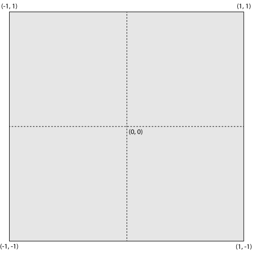
Default drawing coordinates. These are known as NDC or Normalized Device Coordinates.
If you are having difficulty drawing in NDC this week, you can map from canvas coordinates to NDC by changing the
gl_PointCoord line in your vertex shader.
        float width = 500.0, height = 500.0; // set these to match your canvas
        vec4 temp ...; // incomplete - set this with vec4 version of vPosition
                       // exact code depents on how you setup vPosition.

        // if y axis is flipped, use this line
        //temp.y = height-temp.y;
        gl_Position = temp / vec4(width, height, 1., 1.) * 2.0 - 1.0;
This will put (0,0) in the lower left corner of the canvas.
In the last two sections we've discussed how to clear the depth buffer, and the default range of depth values. Perhaps you'd also like to know how to specify 3D vertices and do depth testing.
Without depth testing, objects appear on the screen in the order you draw them. If you want to draw something behind another thing you have already drawn, you need to turn on depth testing, supply depth values with your vertex coordinates, and clear the depth buffer each time you start drawing.
In more detail:
gl.enable(gl.DEPTH_TEST);
vPosition attribute is a vec3 or vec4. Then
make sure you adjust how it is copied to the gl_Position built-in
output.
vec3, then supply a depth, or
z, value to each vertex
in your data arrays. For example you could specify two overlapping triangles like this:
//TRIANGLES
let points=
[
   vec3( 0.0, 0.0,-0.5 ),
   vec3( 0.5, 0.0,-0.5 ),
   vec3( 0.5, 0.5,-0.5 ),
   vec3( 0.0, 1.0, 0.0 ),
   vec3( 0.0,-1.0, 0.0 ),
   vec3( 1.0, 0.0, 0.0 )
];

let colors=
[
   vec4( 1.0, 0.0, 0.0, 1.0 ), // 3 red vertices
   vec4( 1.0, 0.0, 0.0, 1.0 ),
   vec4( 1.0, 0.0, 0.0, 1.0 ),
   vec4( 0.0, 1.0, 1.0, 1.0 ), // 3 cyan vertices
   vec4( 0.0, 1.0, 1.0, 1.0 ),
   vec4( 0.0, 1.0, 1.0, 1.0 )
];
vertexAttribPointer() call for your
position buffer to match
the points array. It was 2, it should be 3 now.If everything works, the cyan triangle in this example appears behind the red, even though it is drawn second. In the default coordinate system, larger z values are farther away. With depth testing off, the cyan triangle would be in front of the red one.
It is good to get a feeling for where you can put points on the scene.
The following instructions are meant to get you started from one of the template projects provided on the lab schedule. Your lab instructor will probably do a. through c. during the lab demo:
init() as indicated by the following comments:
    //Explicitly set clear color to black or a colour you like
    //Load, compile and use a shader
    //Load the simple triangle position data near the top of the notes into a buffer
    //Bind the buffer to your shader's vPosition input
drawArrays() command found in the notes, and place it in the
render()
function as described there.vec2( 0.99, 0.99), vec2(-0.99, 0.99), vec2(-0.99,-0.99), vec2( 0.99,-0.99),
drawArrays() command to draw the four new points:gl.drawArrays(gl.LINE_LOOP, 3, 4); // Start at the fourth vertex, draw four vertices
glUniform*() commands, or set
up and load a colours array as appropriate to accomplish this task.drawArrays() command that draws the triangle. Please leave
the rectangle border in
place./6 - Draw a picture that contains at least three of the various OpenGL primitives. It should look very different from any in-lab demonstrations.
POINTS LINES,
LINE_STRIP, or LINE_LOOP (not including the
line loop in the
instructions above)
TRIANGLES, TRIANGLE_STRIP, or
TRIANGLE_FAN (not including any geometry used as an in-lab demo)
/3 - Use at least 3 different colours. Do this with a uniform shader variable or a vertex colour array input.
/2 - Use at least two point sizes. A uniform must be set up to allow you to set the point size from Javascript.
/2 - Write code that would draw at least two different line sizes. Tell me in a comment whether or not it worked, and on what OS+graphics card combination.
/5 - Artistic impression - your drawing should resemble something and reflect some effort.
sides arguments you can draw
triangles, squares, pentagons,
hexagons, etc. You can learn the size of the array you get back with its .length
member. You can create
a same size colour array with a loop. You can concatenate it with other arrays to add it to your array buffers.
Its points should work well with both LINE_LOOP and TRIANGLE_FAN. TRIANGLES might produce a neat effect too...