Introduction to ARM Assembly Language and Keil uVision5
Objectives
1.	 Introduce some of the ARM architecture to students.

2.	 Begin to use the lab tool - Keil uVision 5.

3.	 The students will create a project and write
 	 an ARM assembly language program based on a simulated target.
The ARM (Advanced RISC Machine) architecture is introduced in the class (also see http://www.arm.com.) Keil MDK-ARM is a complete software development toolkit for ARM processor-based microcontrollers. Keil uVision5 will be used in the lab. The ARM Cortex-M3 processor will be examined with the STM32VLDISCOVERY board. The following is some important information for you.
Important Information
1.      In the lab room CL136, computers are running the Windows Operating System,
        and ARM Software Microcontroller Development Kit Version 5.38a (Keil uVision5) is installed.

2.      To install it in your home computer, you can download the following files:

        MDK538a.EXE - Keil uVision 5 (Version 5.38a)

	301/ftp/uVision5/Keil.STM32F1xx_DFP.2.1.0.pack

3.      To see references of Cortex-M3, visit the following website:
	Cortex-M3 programming manual

4. 	To see STM32VLDISCOVERY board, visit STM32VLDISCOVERY Board.
ARM Architecture
ARM processors are mainly used for low-power and low cost applications such as mobile phones, communication modems, automotive engine management systems, and hand-held digital systems.Here is a diagram of the ARM architecture for your reference.
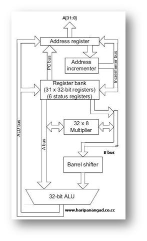
    ARM Architecture is an Enhanced RISC Architecture.
    It has large uniform Register file and uses Load Store Architecture.
       i.e. operations operate on registers and not in memory locations.

    ARM Architecture instructions are of uniform and fixed length.
    It is a 32 bit processor.
    It also has 16 bit variant called THUMB.
       i.e. it can be used as 32 bit and as 16 bit processor.
ARM cores are licensed to partners/manufacturers so as to develop
and fabricate new microcontrollers around same processor cores.
A microcontroller is a small computer on a single integrated circuit
containing a processor core, memory, and programmable input/output peripherals.
The ARM Cortex-M3 microcontroller will be used in the lab with the
STM32VLDISCOVERY board.
For more information, visit STM32VLDISCOVERY Board.
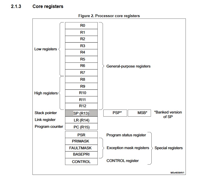
ARM Cortex-M3 Core Registers
Here is the Program Status Register Format:
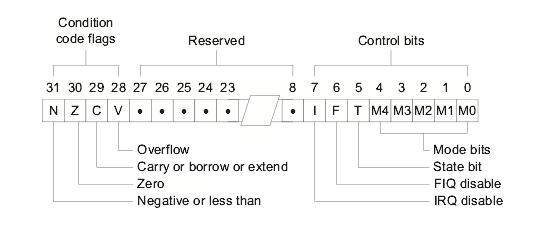
        Conditonion code flags in CPSR:
        N - Negative or less than flag
        Z - Zero flag
        C - Carry or bowrrow or extended flag
        V - Overflow flag
ARM Cortex-M3 Memory Map
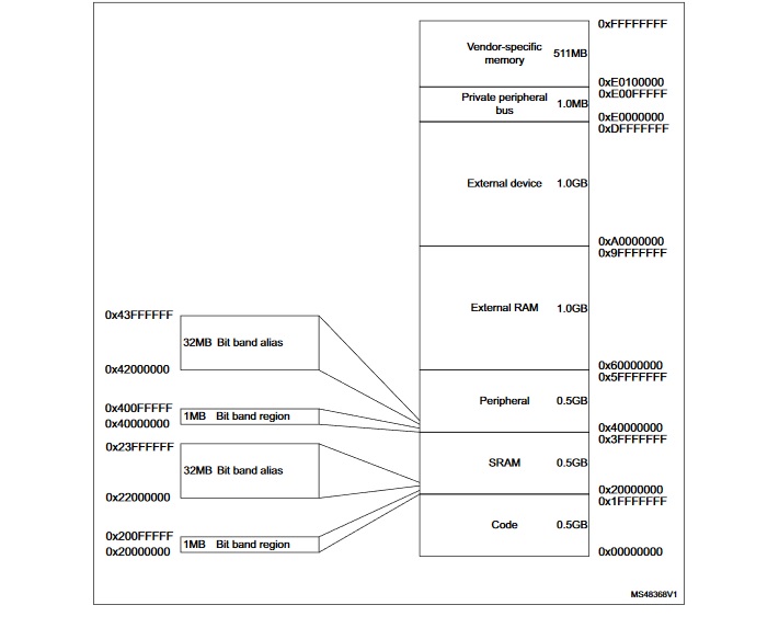
STM32F100xB Memory Map
STM32F100xB Memory Map
STM32F100RB Datasheet
Create an ARM Assembly Language Program
To create an assembly language program, you need to use a text editor such as NotePad in Microsoft Windows environment. There is a text edit in the Keil uVision5 for you to use too. The file name must have a .s at the end. Let's look at the following program called FirstArm.s on a PC. The file FirstArm.s contains the source code of the program to load registers and demonstrate a few other operations. We will use Keil uVision5 to create a project and execute this program so that you can get a feel of how Keil uVision5 works.
;The semicolon is used to lead an inline documentation.
;This is the first ARM Assembly language program you see in the lab.
;This program skeleton was from Dave Duguid and Trevor Douglas.
;When you write your program, you could have your info at the top document block.
;For Example:  Your Name, Student Number, what the program is for, and what it does etc.

;;; Directives
          PRESERVE8
          THUMB

; Vector Table Mapped to Address 0 at Reset
; Linker requires __Vectors to be exported

          AREA    RESET, DATA, READONLY
          EXPORT  __Vectors

__Vectors
	  DCD  0x20001000     ; stack pointer value when stack is empty
			;The processor uses a full descending stack.
			;This means the stack pointer holds the address of the last
			;stacked item in memory. When the processor pushes a new item
			;onto the stack, it decrements the stack pointer and then
			;writes the item to the new memory location.

          DCD  Reset_Handler  ; reset vector

          ALIGN

; The program
; Linker requires Reset_Handler

          AREA    MYCODE, CODE, READONLY

   	  ENTRY
   	  EXPORT Reset_Handler


Reset_Handler
;;;;;;;;;;User Code Starts from the next line;;;;;;;;;;;;

   	  MOV R0, #12

STOP
	  ADD R0, R0, #4
   	  B  STOP

          END	;End of the program
References:
Start up Keil uVision5
Before you start up, you are recommended that you create a folder to hold all your project files.For example: you can have a folder "FirstARM-Project" ready before hand.
You can start up uVision5 by clicking on the icon
 from the desktop or from the "Start" menu or "All Programs" on a lab PC.
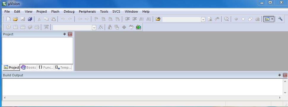
The following screen is what you will see.
Create a project
Let's create our first ARM uVision5 project now.
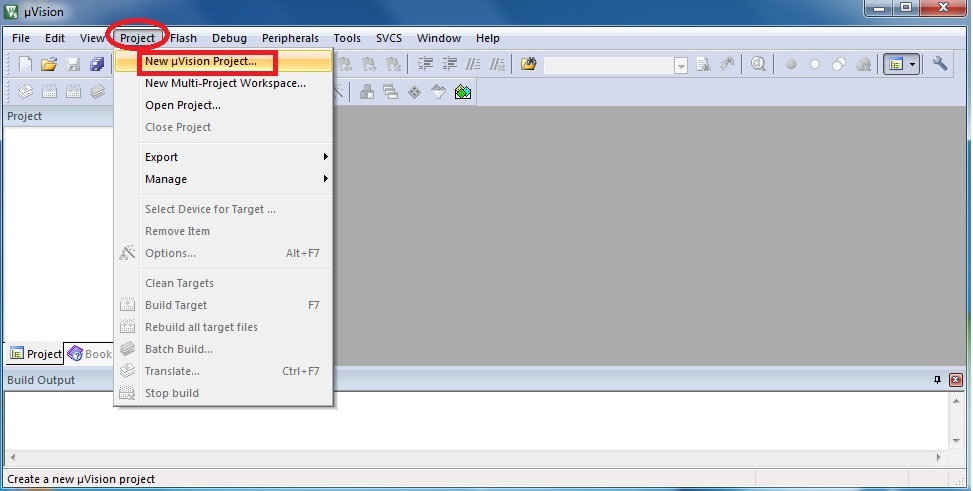
To create a project, click on the "Project" menu from the uVision5 screen
and select "New uVision Project...".
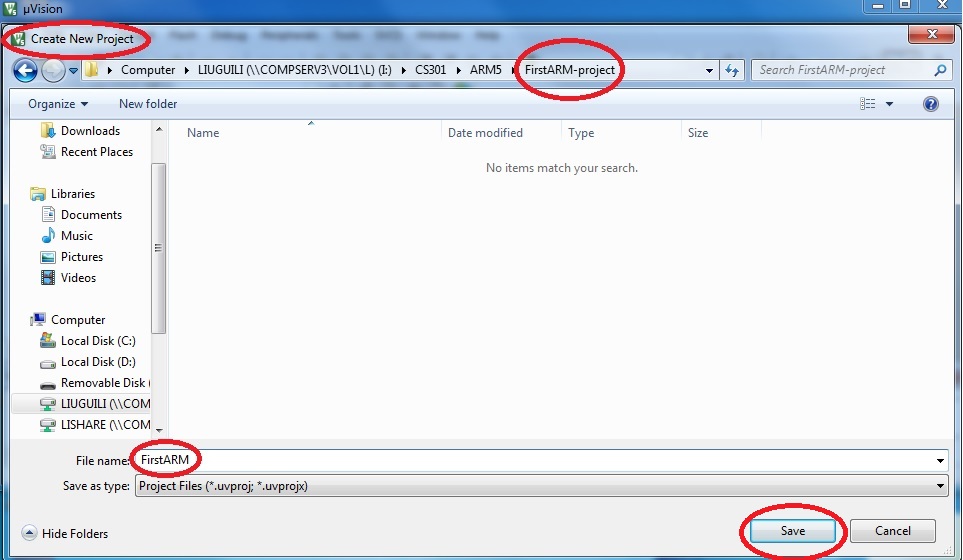
Then, select the folder that you prepared for, give project a name and save it.
From the "Select Device for Target" window, select "STMicroelectronics" and then "STM32F1 Series".
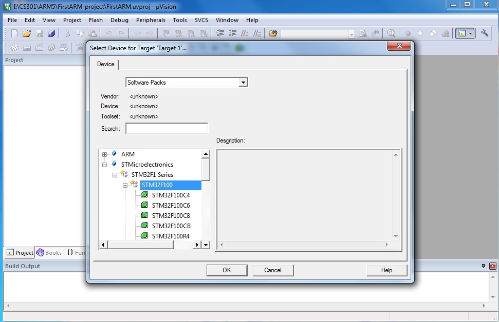
click on "+" beside "STM32F100" and then select "STM32F100RB" and click on "OK".
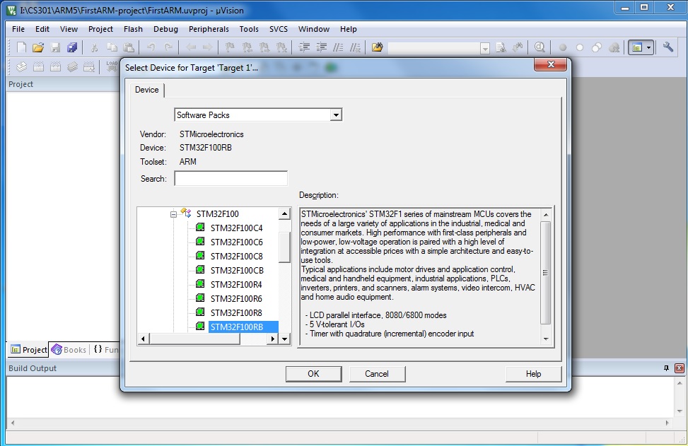
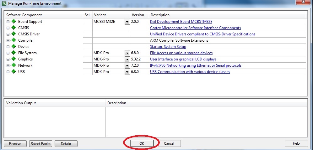
Make sure you click on "OK" for the following pop up window.
Create Source File and Add Source File to the Project
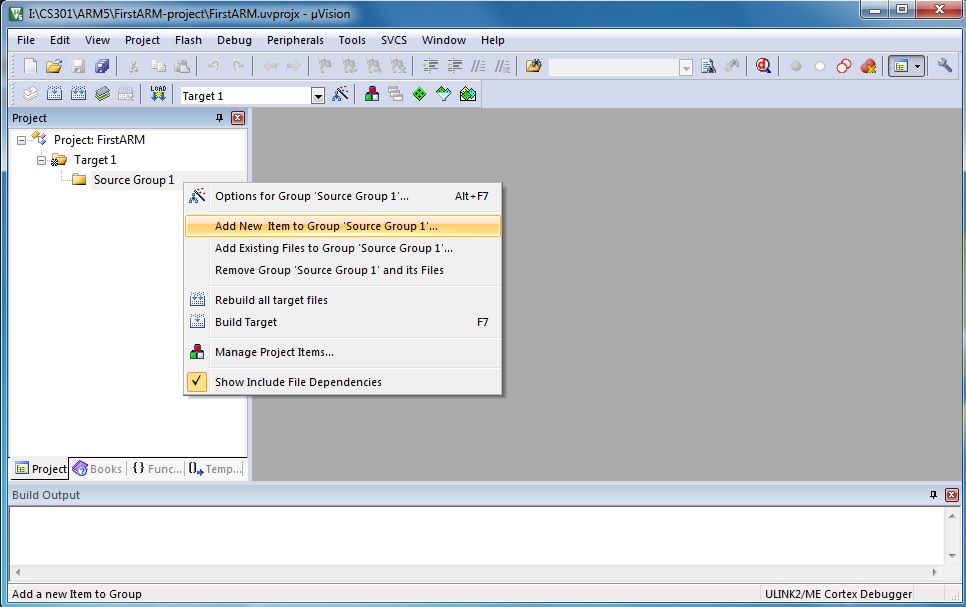
Right click on "Source Group 1" and then select "Add New Item to Group 'Source Group 1'...".
You will see the following window and make the suggested selctions to proceed.
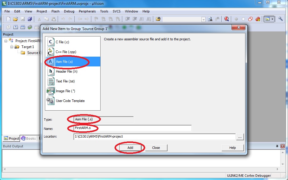
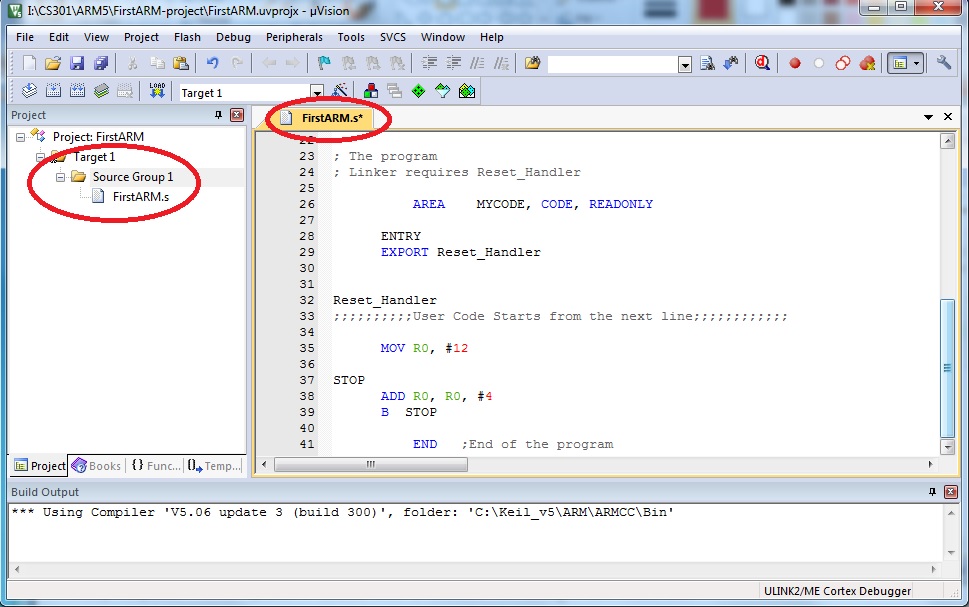
You will see the "FirstARM.s*" text edit window. That is the place you will write your ARM Assembly language program. For a test, you can copy and paste the example program into this window. You can click on the "save" buttom to save your project.
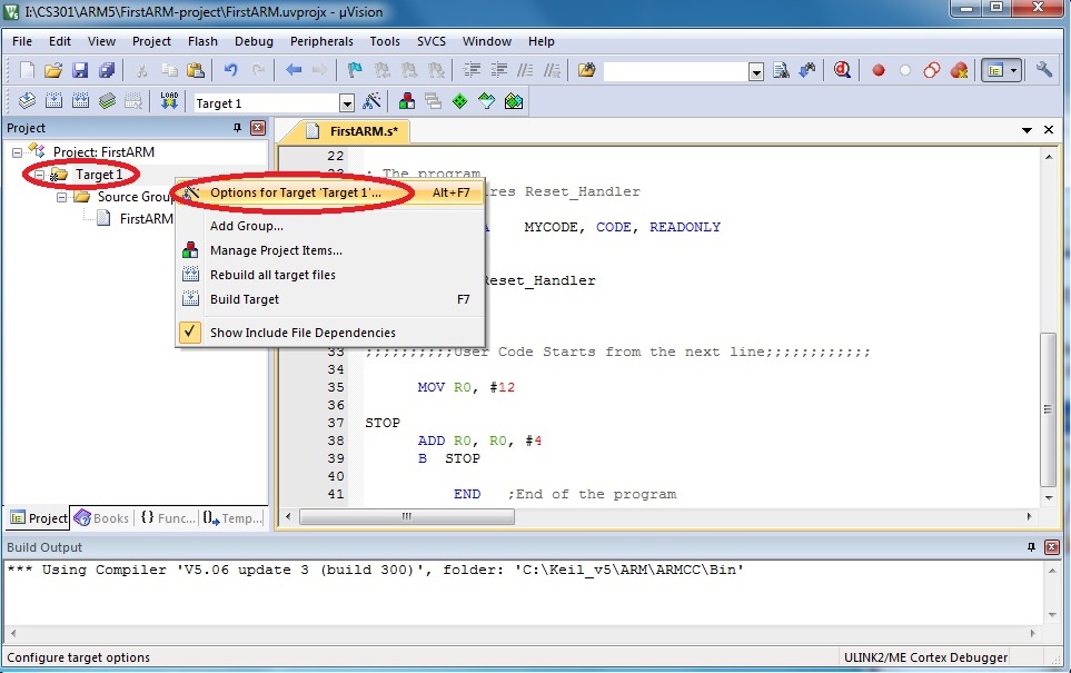
You can right click on "Target 1" and then select "options for Target 'Target 1'..." the same as the following screen.
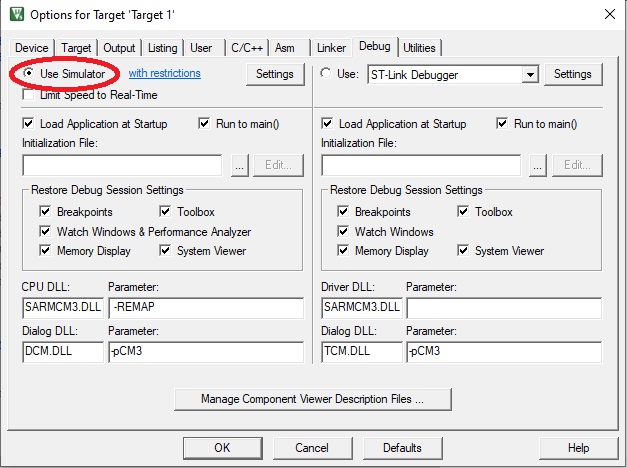
Please click on "Debug" and then select "Use Simulator".
Build your project
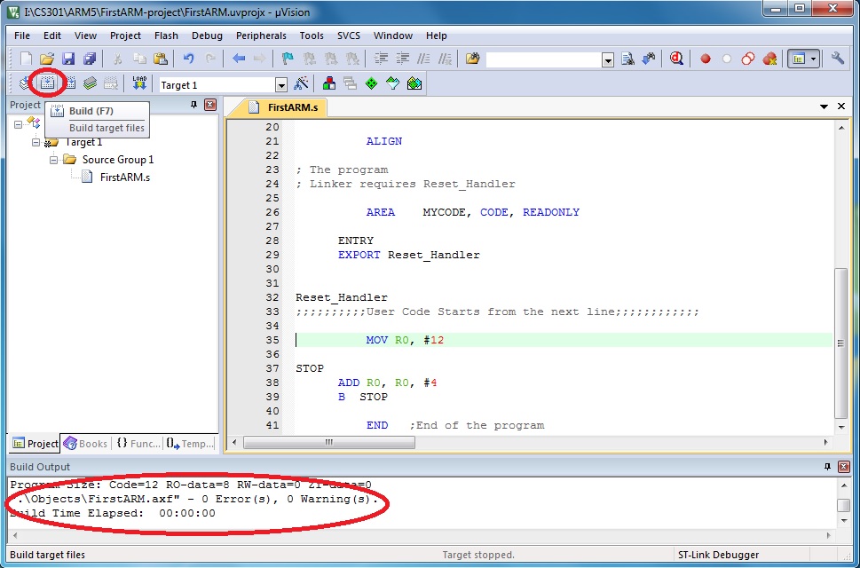
Click on the "Build" button or from the "Project" menu, you will see the following screen.
Run the program in your project
When the assembler is happy with the program, we can run the program by selecting "Start/Stop Debug Session" from the "Debug" menu or clicking on the debug button.
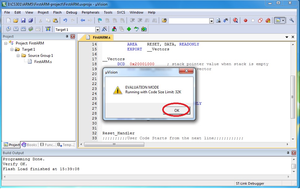
Click on "OK" for the pop up window showing "EVALUATION MODE,
Running with Code Size Limit: 32K".
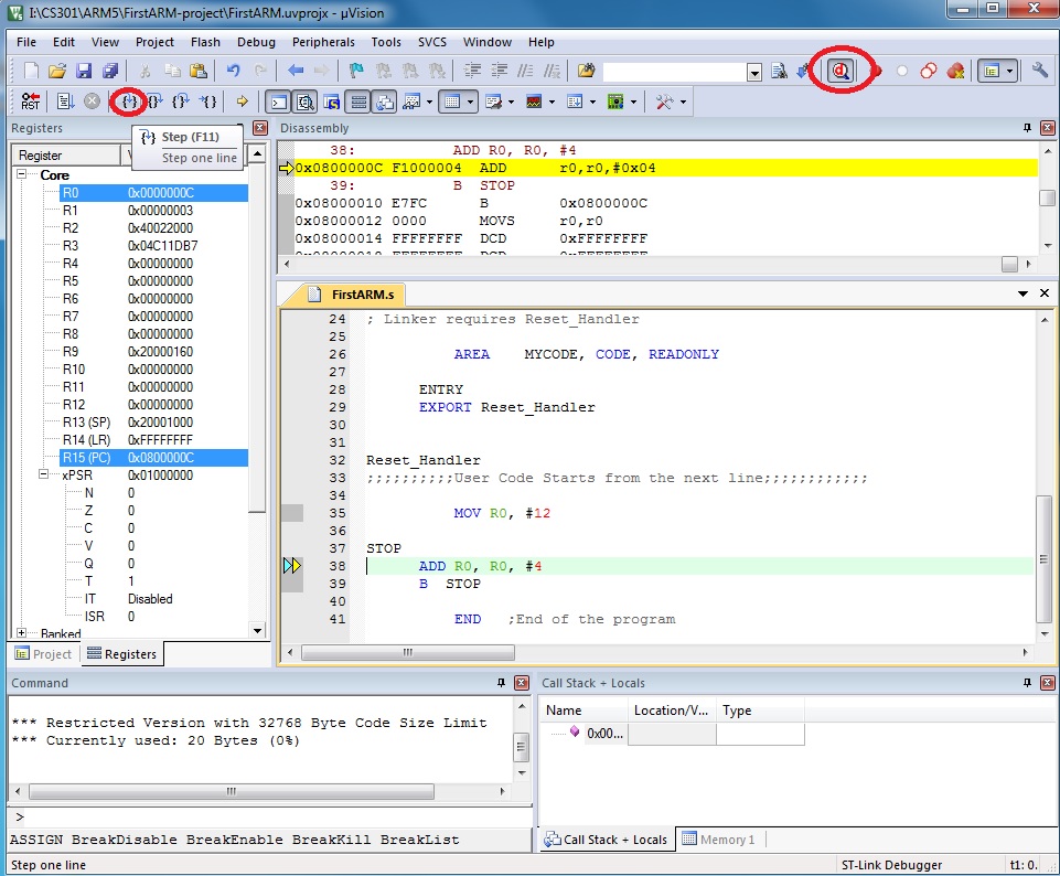
Open your uVision5 to full screen to have a better and complete view.
The left hand side window shows you the registers and the right side
window shows the program code. There are some other windows open.
You may adjust the size of them to see better.
Run the program step by step, you can observe the change of the values
in the registers.
Click on the "Start/Stop Debug Session" from the "Debug" menu or click on the debug button to stop executing the program.
We will analyze the program and see how it works.
It works with both the simulated target and the real circuit board
STM32VLDISCOVERY Board.
I will demonstrate it in the lab for you.
ARM Instructions
Here are a few sample ARM Instructions for you to test out for this lab:
	MOV 	R2, #0x76
	; Move the 8-bit Hex number 76 to the low portion of R2

	MOV 	R2, #0x7654
	; Move the 16-bit Hex number 7654 to the low portion of R2

	MOVT 	R2, #0x7654
	; Move the 16-bit Hex number 7654 to the high portion of R2

	MOV32 	R2, #0x76543210		; Move the 32-bit Hex number 76543210 to the R2

	LDR	R2, = 0x76543210	; Load R2 with the 32-bit Hex number 76543210

	ADD	R1, R2, R3		; R1 = R2 + R3

	ADDS 	R1, R2, R3		; R1 = R2 + R3, and FLAGs are updated

	SUB	R1, R2, R3		; R1 = R2 - R3

	SUBS	R1, R2, R3		; R1 = R2 - R3, and FLAGs are updated

	B	LABEL			; Branch to LABEL
The list of the Instructions above can be found in the Cortex-M3 Devices Generic User Guide, in Chapter 3: The Cortex-M3 Instruction Set.
Lab Assignment
![]() Copyright: Department of Computer Science, University of Regina.
Copyright: Department of Computer Science, University of Regina.