CS201 Lab: Sequential Design
Objectives
- Review the Flip-Flops
- Examine the Sequential Design Procedure
- Build circuits to verify the suquential design procedures
A Note
	We have worked on combinational design; that is the design of
	circuits with no memory. This week we will start to look at
	sequential design, which is the design of circuits with memory.
	Sequential design will let us design much more complicated and
	useful circuits like counters and even microprocessors.
Definition of Sequential Circuits
	Sequential circuits are circuits that have memory.
	In other words, these are circuits where the output depends on
	the current inputs and the previous inputs.

	In combinational circuits the output depends only on the current inputs.
Flip Flops
Flip-Flops are basic storage/memory elements. A sequential circuit consists of a combinational circuit and storage elements (flip-flops) that together form a feedback system. We cannot continue with anymore theory until we look at the basic memory elements used in sequential design. Some of the basic flip-flops are listed below:
- Set-Reset flip flop
The most basic flip flop is the S-R flip flop. (llustrate the operation of the F/F using the diagram below ).
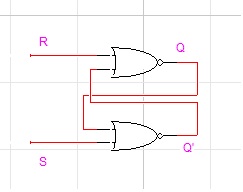
	NOR is 1 iff all inputs are 0.
	S=1 -> Q'=0, but then Q depends on R
	S=1, R=1 -> Q = 0, Q' = 0, Undefined
	R=0, S=1 -> Q = 1, Q' = 0. called "Set"
	R=1, S=0 -> Q = 0, Q' = 1. called "Reset"

	R=0, S=0 -> Q(t+1) = Q(t). called "Hold"

	S R	Q Q'
	------------
	0 0	1 0
	1 0	1 0
	------------
	0 1	0 1
	0 0	0 1
	------------
	1 1	0 0	Undefined
	-------------------------
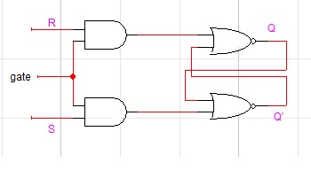
- Gated S-R flip flop
Quite often we only want the flip flop to be able to change states at certain times. For example one may have a flip-flop in an alarm system that is set by a window opening thus setting off the alarm. To prevent the alarm from going off when the alarm system is shut off we would like to disable the flip-flop when the alarm system is shut off. We can do this by adding some gates to a S-R F/F to make it a gated S-R F/F. (Illustrate the operation of the gated S-R F/F using the diagram below ).
In practice S-R F/Fs are not used that often. The most commonly used flip-flops are the D-flip flop and the JK flip-flop. We will look at each one in more details.
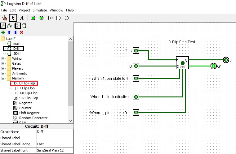
- D flip flop
The D flip-flop(shown below) lets the input at D propogate through to Q on the positive going edge of the clock. The present state-next state chart illustrates the behavior of the D flip-flop. Basically Q(t+1) = D, which is the characteristic equation.
	Characteristic Table		Excitation Table
	====================            ===================
	D  Q(t+1)  Operation            Q(t)  Q(t+1)   D
	====================		===================
	0    0     Reset                 0      0      0
	--------------------            -------------------
	1    1     Set                   0      1      1
	====================            -------------------
					 1      0      0
					-------------------
					 1      1      1
					===================
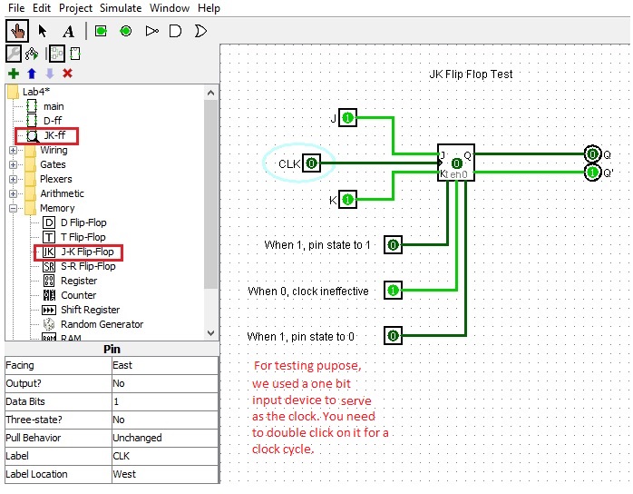
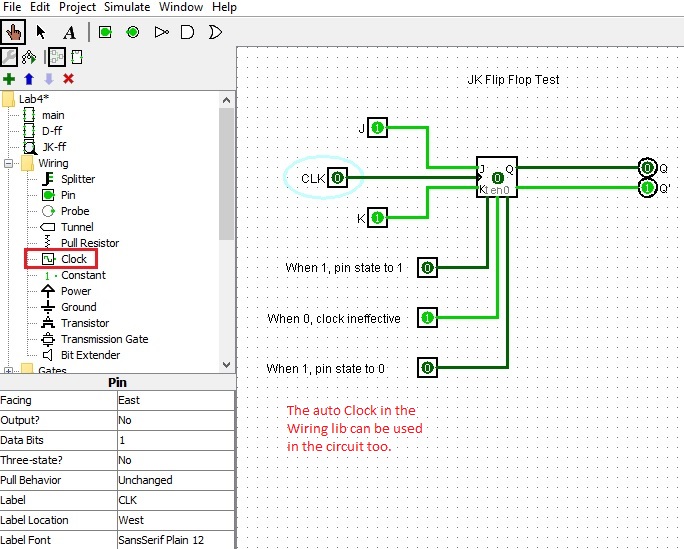
- JK flip-flop
The JK flip-flop in Logisim allows the signal to change on the positive edge of the clock.
The present state-next state chart(shown below) illustrates the behavior of the flip-flop.
The characteristic equation is Q(t+1) = JQ'(t) + K'Q(t).Characteristic Table Excitation Table ========================== =================== J K Q(t+1) Operation Q(t) Q(t+1) J K ========================== =================== 0 0 Q(t) No Change 0 0 0 x -------------------------- ------------------- 0 1 0 Reset 0 1 1 x -------------------------- ------------------- 1 0 1 Set 1 0 x 1 -------------------------- ------------------- 1 1 Q'(t) Complement 1 1 x 0 ========================== ===================
Sequential Design Procedure
1. State the problem clearly 2. Determine inputs/outputs and assign letters to inputs/outputs Determine state bits and assign letters to the state bits 3. Draw a present state-next state diagram 4. Form the state table 5. For each input/output draw the karnaugh maps 6. Find the simplified expressions for the inputs/outputs using Karnaugh maps 7. Draw the logic diagram and implement the circuit in Logisim (a connection diagram would be needed if the circuit is built on hardwired)
Sequential Design Example
We have now covered the basic sequential circuit elements necessary
to construct sequential designs.
We will learn how to interconnect
JK flip-flops to make, for example, counter circuits.
For each flip-flop we must establish what is to be connected to the JK inputs to have that particular bit count properly. We will look at each bit one at a time.
Here is the state table for you to complete:
PresentState NextState C B A C B A JC KC JB KB JA KA ------------------------------------------------------- 0 0 0 0 0 1 0 x 0 x 1 x ------------------------------------------------------- 0 0 1 0 1 1 0 x 1 x x 0 ------------------------------------------------------- 0 1 0 1 1 1 ------------------------------------------------------- 0 1 1 0 1 0 ------------------------------------------------------- 1 0 0 ------------------------------------------------------- 1 0 1 ------------------------------------------------------- 1 1 0 ------------------------------------------------------- 1 1 1 0 0 1 x 1 x 1 x 0 -------------------------------------------------------
Here is some informattion of a JK Filp-flop for your reference.
	Characteristic Table			Excitation Table
	==========================            ===================
	J  K  Q(t+1)  Operation               Q(t)  Q(t+1)  J  K
	==========================	      ===================
	0  0  Q(t)    No Change               0     0       0  x
	--------------------------            -------------------
	0  1  0       Reset                   0     1       1  x
	--------------------------            -------------------
	1  0  1       Set  		      1     0       x  1
	--------------------------	      -------------------
	1  1  Q'(t)   Complement	      1     1       x  0
	==========================	      ===================
Conclusion
	Sequential circuits are circuits that have memory.
	We examined the fundamental sequential circuits like S-R flip-flops
	and JK flip-flops and explained the design steps necessary
	to use these as building blocks for larger sequential circuits.