CS201 Lab: Sequential Design
Objectives of this lab:
	To investigate flip-flop characteristics.
	To verify sequential design procedures by building a simple counter.
Preparation
Read lab lecture notes which contains the Sequential Design Procedure.
Lab Assignments
Please note:To make it easier for marking, you are required to submit
one .pdf file and one .circ file, they will contain all the required components for the lab assignment.
This will apply to Lab #1 to Lab #5.
- Implement the following circuit to test the characteristics of a D flip flop.
- Note:
- Using a clock input to operate the flip-flop is rather quickly.
- You may wish to select the slow motion of the clock OR
to use a simple binary input device instead of a clock input device. - Verify the flip flop state table.
- Q(t+1) = D, is the characteristic equation.
        Characteristic Table            Excitation Table
        ====================            ===================
        D  Q(t+1)  Operation            Q(t)  Q(t+1)   D
        ====================            ===================
        0    0     Reset                 0      0      0
        --------------------            -------------------
        1    1     Set                   0      1      1
        ====================            -------------------
                                         1      0      0
                                        -------------------
                                         1      1      1
                                        ===================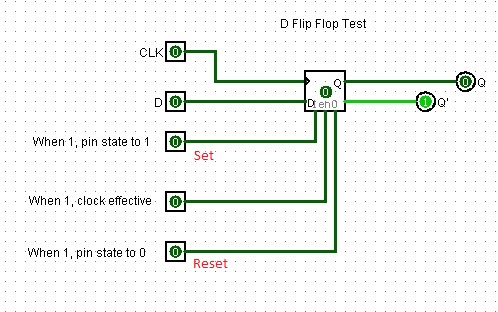
- Questions:
- Is a D flip-flop positive or negative edge triggered?________
- What happens when the Set pin is set to one?__________
- What happens when the Reset pin is set to one?_________
- Does it matter what the D input is when either Set or Reset is one?_________
- Note:
- Experimentally verify the JK flip-flop state table with the following circuit.
Is the JK flip-flop positive or negative edge triggered?________
Verify the Characteristic table.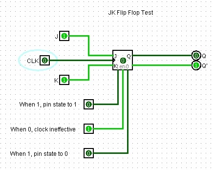
Reference: The characteristic equation of the JK flip-flop is Q(t+1) = JQ'(t) + K'Q(t).
	Characteristic Table                    Excitation Table
	==========================            ===================
	J  K  Q(t+1)  Operation               Q(t)  Q(t+1)  J  K
	==========================            ===================
	0  0  Q(t)    No Change               0     0       0  x
	--------------------------            -------------------
	0  1  0       Reset                   0     1       1  x
	--------------------------            -------------------
	1  0  1       Set                     1     0       x  1
	--------------------------            -------------------
	1  1  Q'(t)   Complement              1     1       x  0
	==========================            ===================
- Design a 3 bit counter which follows the sequence 1 -> 2 -> 3 -> 5 -> 7 -> 1.
-
Note: The following are required for the lab Assignment:
- Follow the sequential design procedure which is presented in the lab lecture notes.
- To make marking easier, route all the unused states to state 7.
- Use JK flip-flops in your counter circuits.
Hand in:- Show your design steps (in the lab notes) and the resulting circuit in Logisim.
Remember to make screenshot and insert the image in you lab4.pdf file. - Describe your testing procedures.
- Show your design steps (in the lab notes) and the resulting circuit in Logisim.
Please note:
To make it easier for marking, you are required to submit the following files:
- One .pdf file and one .circ file, they contain all the required components for the lab assignment.
- Missing any one of the files (.pdf or .circ files) you will get zero for the assignment.
- Submitting with other file format such as .zip or .doc, you will lose 5 marks.
- This will apply to Lab #1 to Lab #5.