CS201 Lab: Integer Multiplier Design
Objectives
- Review Integer Multiplication
- Examine the Hardware Implementation Procedure
- Review the 4-bit Adder device and use it in multiplier circuits
- Review the 4-bit shift register device and use it in multiplier circuits
- Build a 4-bit multiplier circuit and test it
A Note:
	The ALU is an important part of any computer.
	Building an integer multiplier circuit will give us insight of
	how machines could multiply numbers and it will introduce us
	to some of the issues of control unit operation.
Review of Integer Multiplier
- Pencil and Paper Approach
		Here is an example that requires a 2n-bit adder.

			1 0 1 1	  Multiplicand (11)
		      x 1 1 0 1   Multiplier (13)
		----------------
		        1 0 1 1
		      0 0 0 0
		    1 0 1 1	  Partial Products
		+ 1 0 1 1
		----------------
		1 0 0 0 1 1 1 1   Product (143)
	Algorithm  of (M x Q):

	1.	Initilization:
		A (n-bit) = 0;
		C (1-bit) = 0;
		Counter   = n;

	2.	Repeat the following steps until Counter = 0:
		a) If Q0 (LSB of Q) = 1, then C A = A + M,(update C, then load A) and
		   shift C, A, and Q one bit to the right.
		   (Shift the least significant bit of A to Q, and shift the carry bit C to A.)
		b) If Q0 (LSB of Q) = 0, then
		   shift C, A, and Q one bit to the right.
		   (Shift the least significant bit of A to Q, and shift the carry bit C to A.)
		c) Counter = Counter - 1.

	3.	Halt.  The product is in A and Q.
Let's simulate the above algorithm with the example 1 0 1 1 X 1 1 0 1.
	M = 1011,    Q = 1101

	n	C	A	Q	Operations
	----------------------------------------------------------
	4	0	0000	1101	init
	----------------------------------------------------------
	4	0	1011	1101	CA = A + M, Q0 = 1
	3	0	0101	1110	C-A-Q shift right one bit
	----------------------------------------------------------
	2	0	0010	1111	C-A-Q shift right one bit
	----------------------------------------------------------
	2	0	1101	1111	CA = A + M, Q0 = 1
	1	0	0110	1111	C-A-Q shift right one bit
	----------------------------------------------------------
	1	1	0001	1111	CA = A + M, Q0 = 1
	0	1	1000	1111	C-A-Q shift right one bit
	----------------------------------------------------------

	You can see the final product is stored in both A qnd Q registers.
	The register A contains the higher 4-bit and Q contains the lower 4-bit.
		Basic Components:

		a) Register M (n-bit): Stores multiplicand.
		b) Register Q (n-bit): Stores multiplier.
		c) Register A (n-bit): Initialized to zero to store
		   the partial product.
		d) n-bit Adder: Performs addition when Q0 (LSB of Q) is one.
		e) Register C (1-bit):	Holds the end carry of the adder.
		   C, A, Q can be shifted to right simultaneously.
		f) Control Logic:  includes number of iterations and
		   addition and shift operation.
Using 4-bit Parallel Adder
Build the following circuit.
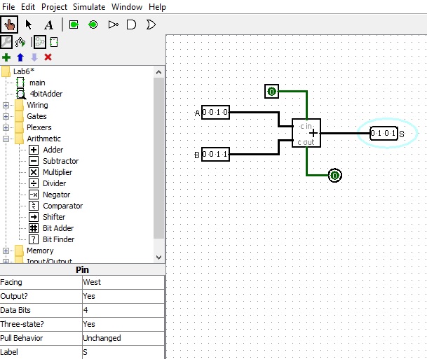
It demonstrates the following: 1. How to use the 4-bit inputs and outputs 2. How to use the 4 bit adder to obtain the sum The initial carry in Cin is 1-bit. The final carry out Cout is 1-bit.
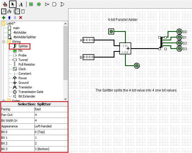
Using a Splitter
        "The splitter creates a correspondence between a multi-bit value and
	several separate subsets of those bits. Despite its name, it can either
	split a multi-bit value into component parts, or it can combine component
	parts into a multi-bit value - or indeed it can do both at once.
	A more complete description of splitters is found in the `Splitters'
	section of the User's Guide."

	The following circuit is a simple demonstration showing you how to use it.
Using 4-bit Shift Register
	The 4-bit shift register has been introduced in the previous lab.
	You need it in your multiplier circuit.  Here is a review.
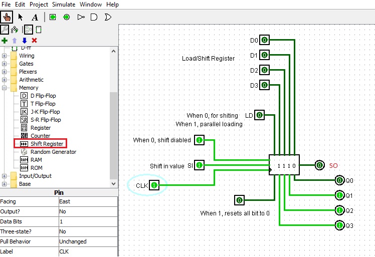
        It demonstrates the following:

                1.      How to use a 4 bit shift register.

                2.      How to use the Load and Shift modes.

                3.      How to show the values on each output bit to make
                        it easier to see what's happening in shift mode.

                4.      Shifting direction is SI->Q3->Q2->Q1->Q0=SO.

        With LD set to 0:

                The register is in shift Right mode;
                The SI (shift in bit) line is used to set the value to be
                shifted into the register. Clocking is positive edge triggered.

        With LD set to 1:

                The register is in parallel load mode.
                Inputs D0 to D3 become outputs Q0 to Q3 on the next
                rising clock pulse.

        It can be used in your multiplier circuit.
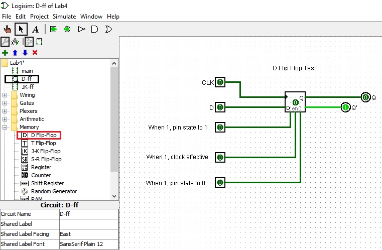
D flip flop review
The D flip-flop(shown below) lets the input at D propogate through to Q on the positive going edge of the clock. The present state-next state chart illustrates the behavior of the D flip-flop. Basically Q(t+1) = D, which is the characteristic equation.
	Characteristic Table		Excitation Table
	====================            ===================
	D  Q(t+1)  Operation            Q(t)  Q(t+1)   D
	====================		===================
	0    0     Reset                 0      0      0
	--------------------            -------------------
	1    1     Set                   0      1      1
	====================            -------------------
					 1      0      0
					-------------------
					 1      1      1
					===================
Algorithm of using the mutiplier circuit
	For the multiplier circuit: You do not build a control unit.
	You will be the brains of the circuit.
	The algorithm to use the circuit will be something like:


	Load up the Q register with the multiplier:
	LD of Q<- 1
	set the input to the 4-bit binery number of the multiplier.
	toggle the Q clock

	Clear the A register:
	LD of A<- 0,   shift 0 in four times.
	toggle the clock until clear
	OR reset the register to 0000.

	Repeat 4 times:
	---------------
	IF (LSB of Q = 1)
	{
	ADD M register to A register:
	toggle the C clock to save the carry bit
	LD of A<- 1
	toggle the A clock

	Shift C__A__Q:
	LD of Q <- 0
	toggle the Q clock
	LD of A <- 0
	toggle the A clock
	}
	ELSE (LSB of Q = 0)
	{
	Shift C__A__Q :
	LD of Q <- 0
	toggle the Q clock
	LD of A <- 0
	toggle the A clock
	}