CS201 Lab: Design Sequential Adders & Subtractors
Objective of this lab:
	To investigate arithmetic circuitry.
	Arithmetic circuits play a central role in the operation of a microprocessor.
Preparation
Read lab lecture notes.
Lab Assignments
Please note: Part1&2 will be marked.
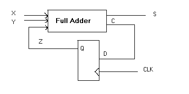
- Obtain the state table, state diagram, and functions of the following sequential design.
Implement the design and verify the state table using your own full adder device.
Use a 4-bit Shift Register to store and display the result of0011 + 0001 ------ 0100
Hand-In- State table
- State diagram
- Functions of sum and carry
- Four Screenshots of the circuit to obtain the results of 0011 + 0001 (stored in the 4-bit Shift Register with MSB and LSB indicated)
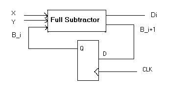
- Obtain the state table, state diagram, and functions of the following sequential design.
Implement the design and verify the state table using your own full subtractor device.
Use a 4-bit Shift Register to store and display the result of0101 - 0011 ------ 0010
Hand-In- State table
- State diagram
- Functions of the difference and borrow
- Four Screenshots of the circuit to obtain the results of 0101 - 0011 (stored in the 4-bit Shift Register with MSB and LSB indicated)
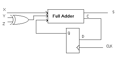
- Implement the following bit sequential Adder-Subtractor design using your own full adder device.

X and Y are two operand inputs and Z is for the control signal i.e. Z is the selection bit.
When Z has value 0, the circuit is an adder, meanwhile, the D flip-flop should be initialized to 0 for each addition.
When Z has value 1, it performs subtraction, meanwhile, the D flip-flop should be initialized to 1 for each subtraction.Test your Adder-Subtractor circuit on the following operations and use the 4-bit Shift Register to store and display their results. (Note: Start from the least significant bit and remember to initialize the D flip-flop accordingly) 0001 + 0011 = ? 0101 + 0010 = ? 0101 - 0011 = ? 0011 - 0101 = ?
Hand-In- Hand in the complete circuits testing the four cases above.
Use a 4-bit Shift Register to store and display their results
and indicate the MSB and LSB. - Describe the testing procedure used for Question 3 for addition and subtraction.
Make sure you have the images of all the completed circuits inserted in the Lab5.pdf file.
Please note:
To make it easier for marking, you are required to submit
one .pdf file and one .circ file, they will contain all the required components for the lab assignment.
This will apply to Lab #1 to Lab #5. - Hand in the complete circuits testing the four cases above.