CS201 Lab: Design Adders & Subtractors
Objectives
- implement a half-adder as a sub-circuit
- implement a full adder using two half adders
- implement a half subtractor as a subcircuit
- use a half-adder to create a half-subtractors
- use the full adders to implement a 4-bit parallel adder
Preparation
- Read the lab notes
- Watch this Adders and Subtractors Tutorial
Lab Assignments
Please note: To make it easier for marking, you are required to submit one .pdf file and one .circ file, they will contain all the required components for the lab assignment. This will apply to Lab #1 to Lab #5.
-
Build the half adder circuit.
Test the circuit and ensure that the truth table is correct.
Write the Boolean functions for sum and carry beside the circuit
Open a new circuit window and test your HalfAdder device/sub-circuit.
Here is a testing circuit for your reference.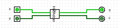
Hand-In- The "Half Adder" circuit
- The HalfAdder device/sub-circuit testing circuit
- Boolean functions for Sum and Carry
- As mentioned in the notes, a full adder can be designed by
using two "Half Adder" devices/sub-circuits
and one additional OR gate.
(Hint ci+1= the sum of the carries out of the two half adders).
Build and test your Fulladder circuit with the truth table.
Write the Boolean functions for sum and the carry beside the circuit.Hand-In
- The full adder circuit using two "Half Adder" devices and one additional OR gate
- Boolean functions for Sum and Carry for the full adder
- A half subtractor subtracts two bits, x and y producing their difference d.
It also has an output b to specify if a 1 has been borrowed from the next higher position.
The truth table is given below.
Draw the "Half Subtractor" circuit, then, test the truth table.
Write the Boolean function for d and b beside the circuit.
InputOutputxybd0000011110011100
Hand-In
- The the "Half Subtractor " Circuit.
- Boolean functions for borrow (b) and difference (d)
- Using the property that:
Show that a half subtractor can be implemented using a "Half Adder" device and two inverter gates.
Build and test this circuit with the truth table.
Write the expressions of the difference and the borrow beside the circuit.Hand-In
- The half subtractor circuit using the "Half Adder" device and two NOT 's
- Boolean functions for Difference and Borrow (will be slightly different from 3, because of inverters--consider what is going into the box and what is coming out of the box)
- Build a 4-bit parallel adder by using four "Full Adder" devices.
For this, you will use the "Full Adder" device from your circuit in the previous step.
Build and test your circuit with the examples:0101 + 0010 ------- ???? 0110 + 0011 ------- ???? and any other examples of your choiceHand-In
- The 4-bit Parallel Adder Circuit using "Full Adder "
devices/sub-circuits with the above two examples and another one of your choice.
Inputs are provided with the one bit input devices. and the outputs will be displayed with the one bit output devices.
- The 4-bit Parallel Adder Circuit using "Full Adder "
devices/sub-circuits with the above two examples and another one of your choice.
Please note:
To make it easier for marking, you are required to submit the following files:
- One .pdf file and one .circ file, they contain all the required components for the lab assignment.
- Missing any one of the files (.pdf or .circ files) you will get zero for the assignment.
- Submitting with other file format such as .zip or .doc, you will lose 5 marks.
- This will apply to Lab #1 to Lab #5.