Figure 1: The color cube with smooth shading selected:
Some of the images shown in the lab notes are from Desktop OpenGL. The original code is available here. Note that this code is very old, and is Windows MFC based.
Download the lab instructor's demos here:
The vectors that you send in to your shaders typically represent colours, vertex coordinates, surface normals, and texture coordinates. Since the components of these vectors have different meanings, GLSL provides special accessors that you can use to refer to the components.
    r, g, b, a    Used for colors. red, green, blue, alpha (blend factor)
    x, y, z, w    Used for spatial coordinates like vectors and points.
    s, t, p, q    Used for texture lookups.
These can be added to the end of a vec* variable to refer to one or more components, or to mix and match them. Consider these GLSL examples:
    vec4 red = vec4(1.0, 0.0, 0.0, 1.0);
    vec2 point2D = vec2(1.0, 0.0);

    //make a yellow color starting with red and matching green to the red component.
    vec4 yellow = red;
    yellow.g = yellow.r;

    //Turn red into blue by rearranging the components (swizzling).
    vec4 blue = red.gbra;

    //Create a partially transparent color from an opaque one.
    vec4 ghostred = vec4(red.rgb, 0.5);

    //Turn a 2D point into a homogeneous 4D point with z = 0.
    vec4 point4D.xy = point2D;
    point4D.zw = vec2(0.0, 1.0);
For more information on accessing and manipulating vector components refer to section 5.5 of the GLSL ES 3.0 Spec. You should also check section 5.1 for a full list of operators, and 5.11 for details on how basic math operators work on matrices and vectors - generally they are component-wise. Be aware of the exceptions like matrix-matrix multiplication.
In this lab you will begin using built-in shader language functions to help with lighting calculations. Here are some should become familiar with.
You can find a complete list of built-in shader commands in section 8 of the
GLSL
ES 3.0 Spec, and you can read more in-depth discussion of their use in the
OpenGL and GLSL API
man pages. The links in the list above go to the man pages for individual functions without the index. You can find other GLSL functions on the main link by looking for names that do not begin with gl.
You can use C/C++ style control flow statements like if-else, switch-case, and for loops. The while, and do-while loops are not always included in WebGL, but they should be there in WebGL 2.
Many of these control flow statements will be used in next week's lighting shader to help support multiple lights. You will also use them in this week's Shader Toy exercises.
There are also a couple simple examples of if statements in this week's lighting shader that allows the use of a simple uniform color for things which should not be lit, and to distinguish positional from directional lights.
The following sections contain a quick review of GLSL control statements, but you should refer to section 6 of the GLSL ES 3.0 Spec for full details.
Functions require prototypes under the same conditions as C++ functions.
Arrays can be passed to functions, but cannot be returned. Arrays are passed to functions as you would expect from C++, but array sizes must be provided in the square brackets of the formal parameter declaration. The argument array must match the size provided in the formal parameter declaration.
Parameters may be qualified as in(default), out or inout. Reference parameters do not exist as such, nor is there any such thing as a reference or pointer in GLSL. You should treat both out and inout qualified parameters as if they were reference parameters.
Overloading of a function name with different parameter types is allowed. Overloading on return type is not, as with C++.
Recursion is not allowed.
Here is an example of typical function prototype and definition structure, from the GLSL specification:
// prototype
returnType functionName (qualifier type arg, qualifier type arg, ...);

// definition
returnType functionName (qualifier type arg, qualifier type arg, ...)
{
    // do some computation
    return returnValue;
}
The main function is the entry point for a shader. It takes no arguments, and must have void return type.
If-Else selection works as you might expect. The conditional expression must evaluate to a boolean. Nesting is allowed.
Switch-Case also works as you might expect. Beware: the compiler allows fall through, but it is an error to have no statement between a case and the end of the switch. Nesting is allowed, but labels and break statements must not appear inside those nested blocks.
You are very lucky to be using GLSL 3.0 ES - it supports for, while and do-while loops more or less as you learned them in C++. Older versions of GLSL had to account for very limited shader hardware, so they put tight restrictions on how you could write loops. I have left the relevant details in the notes for your amusement:
You only get for loops. The GLSL 1.0 ES specification says that while and do-while loops are allowed, but according to Appendix A.4 they are optional in OpenGL ES 2.0 based implementations, so WebGL does not officially support them.
for loops exist, but have some tight restrictions:
int or floatindex relational_operator constant.All of the tight restrictions have been relaxed in GLSL ES 3.0, but the specifications still warns that although "non-terminating loops are allowed, the consequences of very long or non-terminating loops are platform dependent." Ask Alex why...
Structures are simple data type collections. They do not support member functions.
A structure is defined like this:
        struct _light
        {
            vec4 position;
            vec4 color;
        };
Instances of structures are declared like this:
_light light1;
Structures may be const or uniform. They may not be varying or attribute.
You use dot notation to access data members of a structure. If the structure is a uniform, this notation is also the name of that member when you request its location. There is no way to get the location of an entire struct. See the example in L4D2's vertex shader and Javascript code.
Structures may be initialized with a structure constructor. Constant structures must be initialized in this way. The arguments to a structure constructor must be of the same type and in the same order as in the structure's definition. For example:
_light light2 = _light(vec4(1.0, 1.0, 1.0, 0.0), vec4(1.0, 0.0, 1.0, 1.0));
Arrays are similar to C++ arrays, but they must be indexed by a constant valued expression in all but one case - when the array is a uniform. This restriction is not as bad as it sounds, since a for loop index counts as a constant - the tight rules on for loops allow them to be expanded at compile time.
Arrays must also be declared with a constant size.
If an array is a uniform, you get the location of items at its indices individually with the index number as part of the name. There is no way to get a location for an entire array. See the example in L4D2's vertex shader and javascript code.
If the colors of two vertices are different, what is the color between the two vertices? For example, what is the color of the center of the triangle defined by these arrays from lab demo 1?
let points = [
	-1, 0, 0,
	 1, 0, 0,
	 0, 1, 0
];

let colors = [
	 1, 0, 0,
	 0, 1, 0,
	 0, 0, 1
];
The answer is that it depends on the interpolation, or shading, model specified. The choices are smooth and flat.
In WebGL 1.0 there is only smooth shading. In smooth shading, vertex shader outputs are interpolated between vertices on the way to the fragment shader. In the above example the color at the center would be gray.
In WebGL 2.0, you can do flat shading. If flat shading is specified,
one vertex is selected as being representative of all the vertices; thus
the entire primitive is displayed using one single color. For all
primitives it is the last specified vertex in each triangle or line
segment. Flat shading is specified with the keyword flat before
the data type on an output from your vertex shader and the corresponding
input to your fragment shader.
To see the difference between flat and smooth shading, consider the following examples.
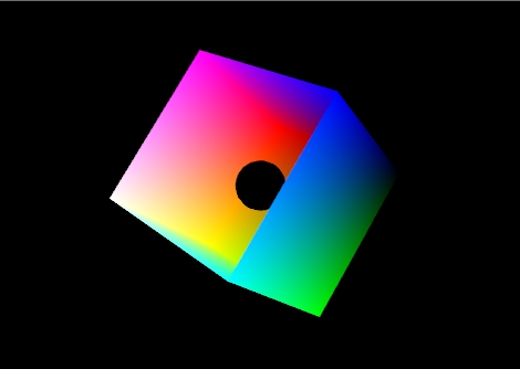
Example 1: a model of a cube missing its top left side. There is a small black ball inside. Specifically it is the RGB color cube. RGB = (0,0,0) is on the right and RGB = (1,1,1) is on the left.
Figure 1: The color cube with smooth shading selected:
Figure 1 shows the effect of smooth shading. With no lighting effects, it is very hard to distinguish between the faces of the polygons that make up the object. Figure 2 shows the same model with flat shading. The color of each face is entirely the result of the order in which the vertices were specified.
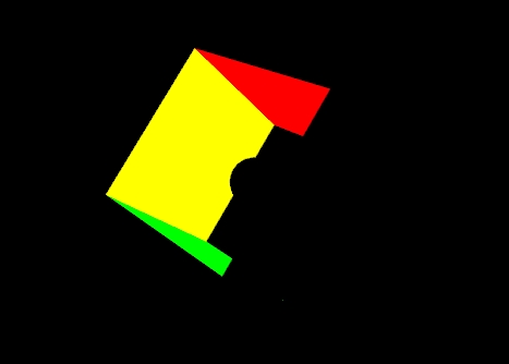
Figure 2: The color cube with flat shading selected.
Your vertex shader can output more than just colour and vertex positions. Any vertex attribute can be interpolated as it is sent to your fragment shader. If you choose to send and interpolate only colours you are doing Gouraud shading. You may also wish to interpolate normals and do lighting calculations in the fragment shader rather than the vertex shader. This is called Phong shading. Do not confuse this with Phong reflection which you can calculate in a vertex shader. You will learn more about Phong reflection calculations in the next lab.
| Flat Shading | Gouraud Shading | Phong Shading | |
|---|---|---|---|
| 10 x 10 (200 triangles) |
|||
| 30 x 30 (1800 triangles) | |||
| 90 x 90 (16,200 triangles) | |||
Figure 1:Torus at different resolutions lit with Blinn-Phong reflection and shaded with different shading models.
Please note: when doing lighting, flat shading does not always light correctly - the normal selected is not automatically adjusted to be perpendicular to the flat shaded primitive. It might look OK, but it will be wrong unless the normal for last vertex of the triangle was calculated to be perpendicular to the triangle.
When you start to work with lighting, you move beyond color to normals, material properties and light properties. Normals describe what direction a surface is facing at a particular point. Material properties describe of what things are made of — or at least what they appear to be made of — by describing how they reflect light. Light properties describe the type, position and colour of the light interacting with the materials in the scene. Lights and materials can interact in many different ways. Trying to accommodate all existing and future methods for calculating lighting is one reason programmable shaders are so important to modern 3D graphics APIs.
You must understand special cases of two basic calculations to be able to perform lighting: the dot product and the cross product.
One common lighting model that relates geometry, materials and lights is the Blinn-Phong reflection model. It breaks lighting up into three simplified reflection components: diffuse, specular and ambient reflection. In this week's lab we will focus on diffuse and ambient reflection.
Diffuse reflection is the more or less uniform scattering of light that you see in matte or non-shiny materials, like paper. The intensity that you see depends solely on the position of the light and the direction the surface is facing. The Blinn-Phong model calculates it using the Lambertian reflectance equation:
Id = md Ld (l · n)
Where:
The dot product between l and n corresponds to the cosine of the angle between the two vectors. If they are the same, then the dot product is 1 and the diffuse reflection is brightest. As the angle increases toward 90° the dot product approaches 0, and the diffuse reflection gets dimmer. This change resembles the how a fixed width of light spreads out over a greater area when it hits a surface at different angles, as illustrated in Figure 4.
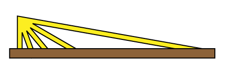
Figure 4: The same width of light covers a larger area as its angle to the surface normal increases.
Even if the light does not reach a point on the surface directly, it may reach it by reflecting off of other surfaces in the scene. Rather than compute all the complex interreflections, we approximate this with ambient reflection. The ambient reflection is a simple product of the ambient colors of both the light and material. Direction does not factor in. The ambient reflectance equation is then:
Ia = ma La
Where:
I = Id + Ia
  #version 300 es
  //diffuse and ambient lighting shader

  //inputs
  in vec4 vPosition;
  in vec3 vNormal;

  //outputs
  out vec4 color;

  //structs
  struct _light
  {
      vec4 diffuse;
      vec4 ambient;
      vec4 position;
  };

  struct _material
  {
      vec4 diffuse;
      vec4 ambient;
  };


  //uniforms
  uniform mat4 p;     // perspective matrix
  uniform mat4 mv;    // modelview matrix
  uniform bool lighting;  // to enable and disable lighting
  uniform vec4 uColor;    // colour to use when lighting is disabled
  uniform _light light; // light properties
  uniform _material material; // material properties

  //globals
  vec4 mvPosition; // unprojected vertex position
  vec3 N; // fixed surface normal

  void main()
  {
    //Transform the point
    mvPosition = mv*vPosition;  //mvPosition is used often
    gl_Position = p*mvPosition;

    if (lighting == false)
    {
          color = uColor;
    }
    else
    {
          //Make sure the normal is actually unit length,
          //and isolate the important coordinates
          N = normalize((mv*vec4(vNormal,0.0)).xyz);

          //Set up light direction for positional lights
          vec3 L;

          //If the light position is a vector, use that as the direction
          if (light.position.w == 0.0)
              L = normalize(light.position.xyz);
          //Otherwise, the direction is a vector from the current vertex to the light
          else
              L = normalize(light.position.xyz - mvPosition.xyz);

          //Calculate diffuse coefficient
          float Kd = max(dot(L,N), 0.0);

          //Calculate colour for this light
          color = Kd * material.diffuse * light.diffuse +
                  material.ambient * light.ambient;
      }
  }
In this week's second lab demo, L4D2, you will update the light structure in the shader using locations stored on a similar light object in Javascript. The following shows how structure member locations are requested from the shader and how they can be given some useful default values:
  // Get  light uniforms
  light = {};   // initialize this light object
  light.diffuse = gl.getUniformLocation(program,"light.diffuse");
  light.ambient = gl.getUniformLocation(program,"light.ambient");
  light.position = gl.getUniformLocation(program,"light.position");

  // Set useful light defaults
  gl.uniform4fv(light.diffuse, vec4(0.8, 0.8, 0.8, 1.0));
  gl.uniform4fv(light.ambient, vec4(0.2, 0.2, 0.2, 1.0));
  gl.uniform4fv(light.position,vec4(0.0, 0.0, 1.0, 0.0));
In this week's second demo, L4D2, only the diffuse and ambient material properties have been
implemented. They have been declared for you globally, given default values and sent to the shader. They
are called material.diffuse and material.ambient. These correspond to properties of the uniform structure called material in the vertex shader.
In that demo let's specify a light blue material. This code should go into your render function just before drawing an object:
    let diffuseColor = vec4(0.5, 0.7, 1.0, 1);
    let ambientColor = scale(0.5,diffuseColor);
    gl.uniform4fv(material.diffuse, diffuseColor);
    gl.uniform4fv(material.ambient, ambientColor);
This is only a little harder than setting a simple uniform colour. For example, shaders that implement specular reflection typically add a separate specular color and a shininess component. The following figure can help you visualize how all these components might interact.
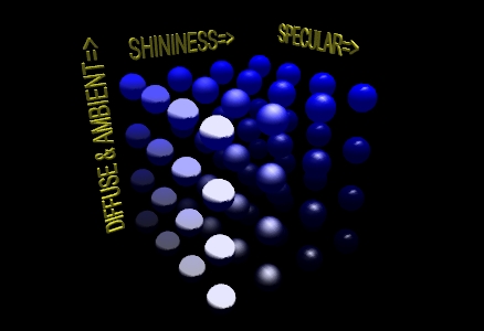
Figure 5: A matrix of spheres showing the range of material properties
To enable lighting in WebGL, you need to write an appropriate shader. To be able to switch lighting on and off, you can use a uniform and an if statement. This lab's lighting shader allows you to enable and disable lighting by writing 1 and 0 respectively to the lighting uniform like this:
   gl.uniform1i(lighting, 0); // disable lighting
   //items you draw will be coloured with uColor

   gl.uniform1i(lighting, 1); // enable lighting
   //items you draw will be lit and be coloured
   //according to relative position of objects, lights,
   //point of view, light and material properties
Each individual light source should have color properties, and a position or direction. It may also have other useful properties.
The shader for this lab supports only one light source, but multiple sources are possible. To enable more than one, you could create an array of _light structures and connect to them all with an loop. This technique is used in the next lab. That lab also guides you through adding new properties to the _light structure to make it more realistic.
The lights in this week's lab have two vec4 colour properties: diffuse, and ambient.
The diffuse component of the light contributes the most to the general reflectance off an object and is what you can consider the "colour" of the light. Shining a light with red diffuse RGBA settings on a white sphere would give a red coloring to all parts of the sphere that the light illuminates.
The ambient component of the light represents the colour the light has after it has bounced around the environment — the environmental colour. It is an approximation the light's contribution to global illumination. It also allows us to see the shape of an object on the dark side. The ambient colour may be the same as the diffuse light colour, or it may be tinted to match the overall colour of the environment.
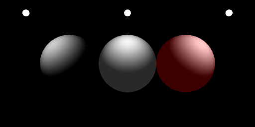
Figure 6: Three identical grey spheres lit by white diffuse and
varying ambient light.
left - only diffuse;
center -
diffuse with matching but dimmer ambient;
right -
diffuse with dim red ambient suggesting a red room.
And here is the code you would used to set up the light colours used on the right sphere in the above example:
    gl.uniform4f(light.diffuse, 1, 1, 1, 1);
    gl.uniform4f(light.ambient, .3, 0, 0, 1);
Each light in this week's lab has a position used to store its position or direction in a vec4. The meaning of the x, y and z is altered by the w component of the vec4:
position.w is 1, the light is positional:position.w is 0, the light is directional:The modelview, mv, matrix is not applied to lights by the shader this means you are responsible for deciding whether you want to apply it in Javascript before setting the light's position uniform. There are two choices here:
Why is this necessary? If the shader applied the modelview matrix to light position, the light would be positioned relative to each individual object rather than appearing to be at one place for the whole frame. The result is very strange.
Examples: try these in render right after the lookAt matrix is calculated.
directional, viewer coordinates: the light appears to be shining onto all objects' right hand side, relative to POV, regardless of position.
    let pos = vec4(1.0, 0.0, 0.0, 0.0);
    gl.uniform4f(light.position, pos);
positional, viewer coordinates: light is to the right of the viewer, like a torch. Its effect depends very much on an object's distance to the viewer's right side.
  let pos = vec4(1.0, 0.0, 0.0, 1.0);
  gl.uniform4f(light.position, pos);
directional, world coordinates: the light is in the +x direction relative to the world. All objects are lit on the same side. The side we see as lit depends on the how we set the lookAt matrix:
  let pos = vec4(1.0, 0.0, 0.0, 0.0);
  gl.uniform4f(light.position, mult(mv, pos));
positional, world coordinates the light is two units to the right of the world origin, and is transformed much like any othe object. It might help to place some geometry at the same position to represent the light:
    let pos = vec4(1.0, 0.0, 0.0, 1.0);
  gl.uniform4f(light.position, mult(mv, pos));
Lighting equations require normals. These are vectors that indicate what direction a surface is facing. For some figures it is easy to calculate the normal. For example the normal for any point on a sphere can be calculated by subtracting the point's coordinates from the sphere's center point. A cube's normals are simply the unit vectors along the major axes - this is what was done in L4D2. Other figures have more complicated normals.
If you have two vectors in the plane perpendicular to a surface you can calculate the normal by taking the cross product of those two vectors. For flat sided figures, you can take any two adjacent edges on a face and use their cross product as the normal for all vertices on the face. For smooth figures, you could take the average of the cross products of all neighboring edges that connect to the vertex. If you know the equation that was used to generate the vertices, you could use derivatives of the equation to calculate the normal.
The following function will take a set of vertices meant for use as TRIANGLES and calculate flat normals for each triangle. You should try it on the cube from the lab notes.
//----------------------------------------------------------------------------
// makeFlatNormals(triangles, start, num, normals)
// Caculates Flat Normals for Triangles
// Input parameters:
//  - triangles: an array of 4 component points that represent TRIANGLES
//  - start: the index of the first TRIANGLES vertex
//  - num: the number of vertices, as if you were drawing the TRIANGLES
//
// In-Out parameters:
//  - normals: an array that corresponds to triangles in length.
//
// Preconditions:
//  - the data in triangles should specify triangles in counterclockwise
//    order to indicate their fronts
//  - num must be divisible by 3
//  - triangles and normals must have the types indicated above
//
// Postconditions:
//  - the normals array will contain unit length vec3s from start,
//    to (start + num) for to match the triangle vertices specified
//    in triangles at those positions
//----------------------------------------------------------------------------
function makeFlatNormals(triangles, start, num, normals) {
    if (num % 3 != 0) {
        throw new Error ("number of vertices is not a multiple of 3");
    }
    if (triangles.length < start+num)
    {
        throw new Error ("triangles array is too short for requested indices");
    }
    if (!Array.isArray(triangles))
    {
        throw new Error ("triangles parameter is not an array");
    }
    if (!Array.isArray(normals))
    {
        throw new Error ("normals parameter is not an array");
    }


    for (let i = start; i < start + num; i += 3) {
        let p0 = vec3(triangles[i][0], triangles[i][1], triangles[i][2]);
        let p1 = vec3(triangles[i + 1][0], triangles[i + 1][1], triangles[i + 1][2]);
        let p2 = vec3(triangles[i + 2][0], triangles[i + 2][1], triangles[i + 2][2]);
        let v1 = normalize(vec3(subtract(p1, p0))); //Vector on triangle edge one
        let v2 = normalize(vec3(subtract(p2, p1))); //Vector on triangle edge two

        let n = normalize(cross(v1, v2));
        normals[i + 0] = vec3(n);
        normals[i + 1] = vec3(n);
        normals[i + 2] = vec3(n);
    }
}
You should always be sure that the normal is of unit length. This is part of the definition of a normal. You should normalize the normal after calculating it. You may also need to rescale or normalize the normal after applying modeling or viewing transformations.
Some transformations will cause the angle between the normal and surface to change. Non-uniform scaling is an example of one such transformation. You will need to correct for this. In the case of non-uniform scaling you need to apply the inverse scale to the normal. To this end, you may want to calculate a separate normal matrix to go along with the modelview matrix.
Lab assignment files are found in Lab4.zip
This exercise is broken into three parts:
Goals:
L4E1.html and L4E1.js. It should seem very familiar.
  let octahedronVertices = [
    vec4(-1, 0, 0,1), //0
    vec4( 1, 0, 0,1), //1
    vec4( 0,-1, 0,1), //2
    vec4( 0, 1, 0,1), //3
    vec4( 0, 0,-1,1), //4
    vec4( 0, 0, 1,1), //5
  ];
gl.TRIANGLES to make each face look flat, especially if you are using the makeFlatNormals function./10
L4E2.html and L4E2.js. It should seem very familiar.vec3(10.0, 0.0, 0.0).E2P1.png. E2P2.png.vec3(0.0, 0.0, 10.0). Note the effect.E2P3.pngE2P4.pngE2P5.pngE2P6.png.Your final submission should have one invisible sphere - it should be completely black. Place comments near your changes to the code. Make sure your have written answers to 2, 5 and 7.
/10
The GLSL shading language is very powerful, and you can write some really interesting stuff with it. Mastering GLSL can be a useful skill in real graphics engines like Unity and Unreal Engine.
The website ShaderToy allows people to share their Shader experiments online. Because ShaderToy uses GLSL 3.0 ES, I am able provide a WebGL template project that is mostly compatible with ShaderToy code. The Art of Code channel on YouTube has some great tutorials to get you started!
Goals:L4E3.html and L4E3_ShaderPlay.frag (find them in Lab4.zip). It's different and exciting!L4E3_ShaderPlay.frag instead of on the ShaderToy website. View your results as you go with L4E3.html