This lab is an introduction to Texture Mapping. It is organized by the following sections:
After the lab lecture, you have until next week to:
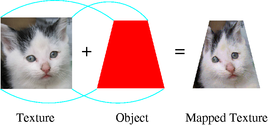
The following diagram represents the idea of texture mapping:
Some definitions:
The idea is that you have multiple images to cover multiple levels of detail. For instance, for an object far away, you have a texture or a mipmap that is small and with little detail, and for closer objects, you have a texture that is large and detailed.
Taking an example from msdn (Search for EasyTex). If you are looking at a stop sign from far away, you see only a red circle. As you get closer, you can see it is a red shape with some letters. Finally, you see the entire stop sign. You might specify the mipmaps to look something like this:

If you did not specify different levels of detail, OpenGL would try and squish the large stop sign into a smaller image. It would combine the red sign with the white letters, and you would get a pink blob instead of a round, red circle.
The Steps in Texture Mapping are the following
To begin with, we need a texture name. Texture names are numbers that OpenGL uses to identify or index the textures. Your version of OpenGL may allow you to use any unsigned integer, but using glGenTextures() is required by the newer OpenGL specifications. Even if it is not required, it is still a good idea to use it because glGenTextures() generates valid, unused texture names. You can generate one name at a time into simple unsigned integers, or many into an array of unsigned integers. The code to generate one name into an unsigned integer looks like this:
    GLuint texName
    //allocate a texture name
    glGenTextures(1, &texName);
We now have a texture name (or unique index), now we want to specify what texture we are working with. There are three forms of textures in OpenGL, 1D, 2D and 3D. In this lab, we will be working with 2D, this is reflected in the GL_TEXTURE_2D in the following code:
    //select our current texture
    glBindTexture(GL_TEXTURE_2D, texName);
By issuing the glBindTexture() for the first time with texName, we are creating a texture object which is 2D and contains some initial default values or properties.
You will notice that we will call glBindTexture() again later with texName. When glBindTexture() is called with a previously created texture object, that texture object becomes active. Therefore, the next call to glBindTexture() will make texName the active or current texture state.
We've got a texture name and we've created a texture with the glBindTexture() command, now we can specify some properties or parameters for the texture. If we don't specify any parameters, the default values will be used.
The following may be some parameters that we want to set. The comments provide some idea as to what each of these calls is doing. For more details about these parameters, you might want to consult the manual for glTexParameter .
    //The texture wraps over the edges (repeats) in the x direction
    glTexParameteri(GL_TEXTURE_2D, GL_TEXTURE_WRAP_S, GL_REPEAT);

    //The texture wraps over the edges (repeats) in the y direction
    glTexParameteri(GL_TEXTURE_2D, GL_TEXTURE_WRAP_T, GL_REPEAT);

    //when the texture area is large, repeat texel nearest center
    glTexParameteri(GL_TEXTURE_2D, GL_TEXTURE_MAG_FILTER, GL_NEAREST);

    //when the texture area is small, repeat texel nearest center
    glTexParameteri(GL_TEXTURE_2D, GL_TEXTURE_MIN_FILTER, GL_NEAREST);
Next, we can specify the image we are going to use. Assuming that we have an image (checkImage) which is a 2 dimensional checkerboard pattern which is stored in a three dimension array containing RGBA components. We can set the texture to the checkImage with the following code:
glTexImage2D(GL_TEXTURE_2D, 0, GL_RGBA, checkImageWidth, checkImageHeight,
                            0, GL_RGBA, GL_UNSIGNED_BYTE, checkImage);
See the online OpenGL 3.3 man page for glTexImage2D, and Figures 1, 2, and 3 (my copies since they are missing from the first link).
While you are drawing, you need to specify which texture you are going to be working with. You can have multiple textures loaded into your Rendering Context. You switch between them by calling glBindTexture. Remember, the first time you call glBindTexture it creates a texture object with default values for the texture image and texture properties. You can then load a texture and configure it. The second time you call it with the texture name, that texture data becomes the current texture state.
glBindTexture(GL_TEXTURE_2D, texName);
You have to specify which part of our texture image are going to fit or map onto the object. Texture coordinates are often referred to as s and t. For a texture image, s and t are in the range of 0 to 1. The mapping itself is similar to setting a color for each vertex. To map the checkerboard texture onto a square, we would provide vertex and texture coordinate arrays that would look like this:
vec3 points[] =
{
        //square
	-2.0, -1.0,  0.0,
	 0.0,  1.0,  0.0,
	-2.0,  1.0,  0.0,

	-2.0, -1.0,  0.0,
	 0.0, -1.0,  0.0,
	 0.0,  1.0,  0.0,
};

vec2 texCoords[] =
{
        //square
	0.0,  0.0,
	1.0,  1.0,
	0.0,  1.0,

	0.0,  0.0,
	1.0,  0.0,
	1.0,  1.0,
};
Graphically, we could see the mapping as the following:
To use a texture you must declare a uniform of type sampler* in your fragment shader. Samplers come in 1D, 2D and 3D flavours. You will be using sampler2d. The sampler is used to help look up values in a texture correctly. Each sampler in your shader program will be connected to a single texture image unit. You can connect to up to 48 in most modern OpenGL implementations. Older implementations only guarantee 2. For starters you will only be using one texture image unit, and that is unit 0.
uniform sampler2D tex;
    //The default texture image unit is unit 0
    glUniform1i(glGetUniformLocation(program1, "tex"), 0);
As you write more advanced programs, you may wish to use more than one texture at the same time to achieve certain effects such as adding detail, bump mapping or gloss mapping. To do this generate, bind, set parameters, and load data into multiple texture names, then you bind them to multiple texture image units and send their numbers to the shader like this:
    //Configure two separate texture names, just like for simple texturing
     .
     .
     .
    //Connect the numbers of the texture units you plan to use to samplers in the shader
    glUniform1i(glGetUniformLocation(program1, "tex0"), 0);
    glUniform1i(glGetUniformLocation(program1, "tex1"), 1);
    //Bind texture names to texture units
    glActiveTexture(GL_TEXTURE0); //switch to texture image unit 0
    glBindTexture(GL_TEXTURE_2D, textures[0]);   //Bind a texture to this unit
    glActiveTexture(GL_TEXTURE1); //switch to texture image unit 1
    glBindTexture(GL_TEXTURE_2D, textures[1]);   //Bind a different texture to this unit

   //Draw textured item
   ...
Note that glActiveTexture takes OpenGL constants of the form GL_TEXTUREn whereas you only send the number, n, of the texture unit to the sampler in the shader. OpenGL 3.2 specifies a minimum of 48 texture units, so n can be a value from 0 through 47 if you have full OpenGL 3.2 Core profile support.
#version 150

in vec2 TexCoord;
uniform sampler2D tex;
out vec4 fColor;

void main()
{
	fColor = texture(tex, TexCoord);
}
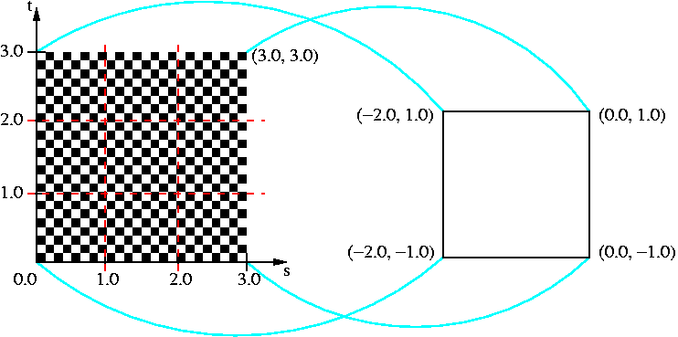
In the example that we are using, we have specified that we would like to repeat the pattern, but we are currently not making use of this repeating feature. When we repeat a texture, it provides a "tile" effect. The following code specifies that we will repeat the texture map.
    glTexParameteri(GL_TEXTURE_2D, GL_TEXTURE_WRAP_S, GL_REPEAT);
    glTexParameteri(GL_TEXTURE_2D, GL_TEXTURE_WRAP_T, GL_REPEAT);
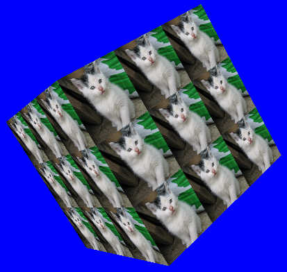
But in order to see any results, we have to assign texture coordinates outside the range [0,1]. For instance to get a 3x3 tile of the checkerboard on our square, we would specify the texture coordinates like this:
vec2 texCoords[] =
{
        //square
	0.0,  0.0,
	3.0,  3.0,
	0.0,  3.0,

	0.0,  0.0,
	3.0,  0.0,
	3.0,  3.0,
};
Try it out!
Graphically, we could see the mapping as the following (the red lines are placed in the texture map to help show that the texture is repeated three times)
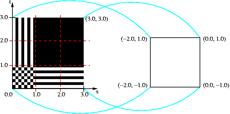
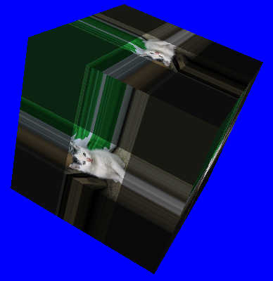
Instead of specifying that we want to repeat the texture, we can specify that we want to clamp the texture. In this case, we change the GL_REPEAT to GL_CLAMP_TO_EDGE.
   glTexParameteri(GL_TEXTURE_2D, GL_TEXTURE_WRAP_S, GL_CLAMP_TO_EDGE);
   glTexParameteri(GL_TEXTURE_2D, GL_TEXTURE_WRAP_T, GL_CLAMP_TO_EDGE);
What does this mean? Any values greater than 1.0 are set to 1.0, and any values less than 0.0 are set to 0.0. For instance, if we use GL_CLAMP_TO_EDGE with the above texture coordinates, then a small copy of the texture will appear in the bottom left-hand corner of the object. To the right will be a "clamp" of the texture at s=1. To the top, will be a clamp of t=1.
Graphically, we could see the mapping as something like this (again, the red lines are in the image to point out the original texture in the bottom left-hand corner).
The checkerboard pattern in the above example was a simple black and white image that we stored into a three dimensional array. We may want to use more complicated pictures--for instance, images that we have taken or scanned.
There are several graphics file formats. OpenGL does not come with any image loading utilities, but if we have an image loading library, we can read from them and use them for our texture map. This lab uses FreeImage, an open source cross platform image loading library that supports a wide variety of image types. The library has been included in your exercise project as a static library for your convenience.
FreeImage is easy to use, but to make it even easier this lab wraps it with the Image class found in IMGLoader.[h|cpp]. To use it, simply create an Image object and .open() an image by name. The object will store width (sizeX), height (sizeY) and pixel data (data) for the currently open image. You may use the same object to open any number of images one at a time. See the exercise for an example of its use. If you provide a palettized image, it will be converted to either 24 or 32-bit by the loader based on whether it has transparency.
One interesting quirk of FreeImage is that it stores data in BGR or BGRA byte order, rather than in the RGB or RGBA order that you might expect and that OpenGL uses internally. This byte order is preserved in the Image class's data member. Fortunately, OpenGL provides a compatible image format specifier. You should specify GL_BGR for 24-bit images and GL_BGRA for 32-bit images.
If you prefer not to use a library, or would like to try writing your own texture loader, Windows .BMP format for 24-bit images is pretty easy to figure out since no de-compression or palette lookup tables are involved. This lab used to have a custom BMP loader, which you can see in this old version of this lab's exercise. The notes that follow can help you understand how it works.
Windows bitmap files are stored in a device-independent bitmap (DIB) format that allows Windows to display the bitmap on any type of display device. The term "device independent" means that the bitmap specifies pixel color in a form independent of the method used by a display to represent color. The default filename extension of a Windows DIB file is .BMP.
(From: http://www.dcs.ed.ac.uk/home/mxr/gfx/2d/BMP.txt)
You can summarize the bitmap as containing four chunks of information or data:
The first bytes in the file contain the header information (1, 2, and 3 in the list above), then subsequent bytes contain the RGB components of each pixel in the image.
To summarize the header information, the first 14 bytes contain the BITMAPFILEHEADER,
which is broken down into:
| 2 bytes | type of file which must be BM |
| 4 bytes | size of the file |
| 2 bytes | reserved1 which must be 0 |
| 2 bytes | reserved2 which must be 0 |
| 4 bytes | byte offset from the BITMAPFILEHEADER structure to the actual bitmap data in the file |
The next 40 bytes contain the BITMAPINFOHEADER, which is broken down into:
| 4 bytes | number of bytes required by the BITMAPINFOHEADER |
| 4 bytes | width of the bitmap in pixels |
| 4 bytes | height of the bitmap in pixels |
| 2 bytes | number of planes for the target device (must be 1) |
| 2 bytes | number of bits per pixel. In our example, it must be 24. |
| 4 bytes | type of compression for a compressed bitmap |
| 4 bytes | size, in bytes of the image |
| 4 bytes | horizontal resolution, in pixels per meter |
| 4 bytes | vertical resolution, in pixels per meter |
| 4 bytes | number of color indexes in the color table actually used by the bitmap |
| 4 bytes | number of color indexes that are considered important for displaying the bitmap |
Next is the color table, for our example, there is no color table because each pixel is represented by 24-bit red-green-blue (RGB) values in the actual bitmap data area.
Finally is the bitmap data area. It consist of a series of BYTE values representing consecutive rows, or "scan lines," of the bitmap. Each scan line consists of consecutive bytes representing the pixels in the scan line, in left-to-right order. The first byte represents the pixel in the lower left-hand corner of the bitmap.
I have explained all this to give you a little more understanding for the code in this lab's exercise. The key thing to know is that most of the header information for the bitmap is skipped. The height and the width of the bitmap are extracted to allow you to load images of varying sizes. Then, the RGB components are stored into a dynamically allocated array (data), which is part of the Image structure. Another thing to note is that .BMP files store their color information in Blue-Green-Red order. For OpenGL, the order is changed to Red-Green-Blue.
Although it would appear that your texture images can be of any size you wish, for maximum compatibility (see Issue #2) you should use images with both the width and height a power of 2. For instance, valid sizes would be: 64 x 16, 512x512, 256 x 256, 128 x 128, and 16 x 4. Whereas invalid sizes would be: 100 x 100, 6 x 4, 5 x 5, and 2 x 22. This compatibility issue comes up with OpenGL ES 2.0, which only supports non-power-of-two textures if they are clamped and not mipmapped.
If you do have an odd size image, you can use the gluScaleImage() function in your code. Refer to the Online OpenGL manual.
The following are a list of references which were used in the making of this lab:
Goals:
This week's lab exercise was originally based on Lesson 6 from NeHe OpenGL tutorials. It has been mostly rewritten, but still uses some textures provided in that tutorial.
Start with the appropriate version of the Lab5Exercise project for your platform: MAC or PC
Modify the code by following these steps:
(TOTAL /10)
BONUS: Specular Mapping and MultitexturingNotice that the fragment shader receives two colours from the vertex shader - one for diffuse and ambient, and another for specular. Both are added together then multiplied by the texture colour. This hides spcular highlights when the texture is dark. If you only multiply the texture against the diffuse and ambient colour, you can see the specular highlight across the surface of the whole cube. It is possible to use a second texture to control specular colour.
To do this bonus: