Some of the examples mentioned in the lab notes are available here. Note that this code is very old, and is Windows MFC based.
Download the lab instructor's demos here:
The vectors that you send in to your shaders can represent colours, vertex coordinates, vectors, and texture coordinates (more on this next lab). Since the components of these vectors have different meanings, GLSL provides special accessors that you can use to refer to the components.
    r, g, b, a    Used for colors. red, green, blue, alpha (blend factor)
    x, y, z, w    Used for spatial coordinates like vectors and points.
    s, t, p, q    Used for texture lookups.
These can be added to the end of a vec* variable to refer to one or more components, or to mix and match them. Consider these examples:
    vec4 red = vec4(1.0, 0.0, 0.0, 1.0);
    vec2 point2D = vec2(1.0, 0.0);

    //make a yellow color starting with red and matching green to the red component.
    vec4 yellow = red;
    yellow.g = yellow.r;

    //Turn red into blue by rearranging the components.
    vec4 blue = red.gbra;

    //Create a partially transparent color from an opaque one.
    vec4 ghostred = vec4(red.rgb, 0.5);

    //Turn a 2D point into a homogeneous 4D point with z = 0.
    vec4 point4D.xy = point2D;
    point4D.zw = vec2(0.0, 1.0);
Accessing and modifying vectors in this way is called swizzling. Try swizzling the colours and coordinates for the triangle in lab demo 1.
Dr. Angel's vec library for C++ only defines simple accessors for components, but you can use color, spatial coordinate and texture coordinate names as needed.
In this lab we will be using various built-in shader language functions to help with lighting calculations. Here are some of the commands you should become familiar with. You can learn all about shader commands by referring to the GLSL Reference Pages.
You can use C/C++ control flow statements like if-else, switch-case, for, while, and do-while. There is a simple example of this in the lighting shader that allows the use of a simple color for things which should not be lit.
If the colors of two vertices are different, what is the color between the two vertices? For example, what is the color of the center of the triangle defined by these arrays from lab demo 1?
GLfloat points[] =
{
	-1, 0, 0,
	 1, 0, 0,
	 0, 1, 0
};

GLfloat colors[] =
{
	 1, 0, 0,
	 0, 1, 0,
	 0, 0, 1
};
The answer is that it depends on the interpolation, or shading, model specified. If smooth shading(default) is specified, the color values are interpolated between vertices. In this case the color at the center would be gray. If flat shading is specified, one vertex is selected as being representative of all the vertices; thus the entire primitive is displayed using one single color. For all Core Profile primitives primitives it is the last specified vertex in each polygon or line segment. Older style primitives had some exceptions to this rule.
In a shader you can specify flat shading by using the keyword flat before the data type on an output from your vertex shader and corresponding input to your fragment shader.
Shader language 1.2 and earlier do not have the flat keyword and flat shading is impossible to do in a shader, though it is possible to do it if you use fixed functionality in compatibility mode..
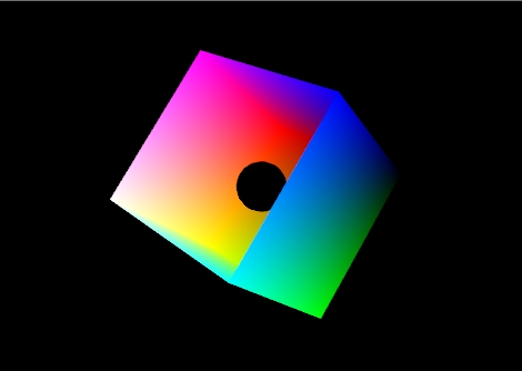
Take the following example. The model is a cube with the top left off and a small black ball inside. Specifically it is the RGB color cube. RGB = (0,0,0) is on the right and RGB = (1,1,1) is on the left.
|
|
| Figure 1: The color cube with smooth shading selected: |
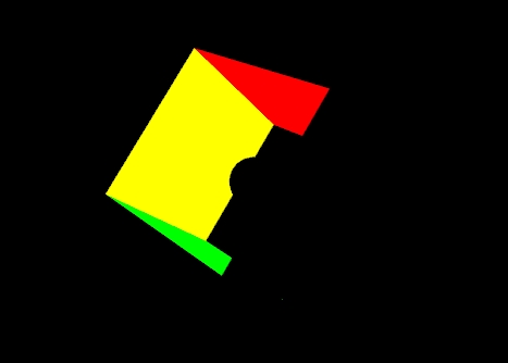
Figure 1 shows the effect of smooth shading. With no lighting effects, it is very hard to distinguish between the faces of the polygons that make up the object. Figure 2 shows the same model with flat shading. The color of each face is entirely the result of the order in which the vertices were specified.
 |
|
Figure 2: The color cube with flat shading selected. |
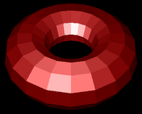
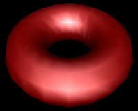
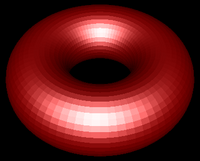
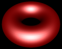
Your vertex shader can output more than just colour and vertex positions. Any vertex attribute can be interpolated as it is sent to your fragment shader. If you choose to interpolate colours you are doing Gouraud shading. You may also wish to interpolate normals and do lighting calculations in the fragment shader rather than the vertex shader. This is called Phong shading, which is not to be confused with Phong reflection.
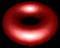
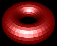
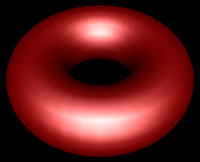
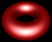
| Flat Shading | Gouraud Shading | Phong Shading |
|---|---|---|
 |
 |
 |
 |
 |
 |
 |
 |
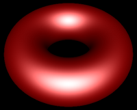 |
| Figure 3:Torus at different resolutions lit with Blinn-Phong reflection and shaded with different shading models. | ||
When you start to work with lighting, you move beyond color to normals, material properties and light properties. Normals describe what direction a surface is facing at a particular point. Materials properties are descriptions of what things are made of -- or at least what they appear to be made of -- by describing how they reflect light. Light properties describe the type and colour of the light interacting with the materials in the scene. Lights and materials can interact in many different ways. Describing these many different ways is one reason shaders are so important to modern 3D graphics APIs.
One common lighting model that relates geometry, materials and lights is the Blinn-Phong reflection model. It breaks lighting up into three simplified reflection components: diffuse, specular and ambient reflection. The following discussion will help you understand the calculations in the shader code, but it is simplified. You should refer to class lectures or your textbook for details.
Diffuse reflection is the more or less uniform scattering of light that you see in matte or non-shiny materials. The intensity that you see depends solely on the position of the light and the direction the surface is facing. The Blinn-Phong model calculates it using the Lambertian reflectance equation:
Id = md Ld (l · n)
Where:
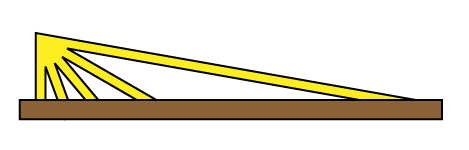
The dot product between l and n corresponds to the cosine of the angle between the two vectors. If they are the same, then the dot product is 1 and the diffuse reflection is brightest. As the angle increases toward 90° the dot product approaches 0, and the diffuse reflection gets dimmer. This change resembles the how a fixed width of light spreads out over a greater area when it hits a surface at different angles, as illustrated in Figure 4.
 |
|---|
| Figure 4: The same width of light covers a larger area as its angle to the surface increases. |
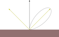
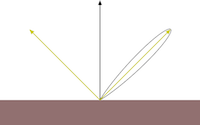
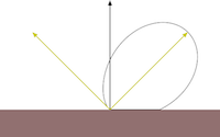
Specular reflection represents the shine that you see on very smooth or polished surfaces. Phong specular reflection takes into account both the angle between your eye and the direction the light would be reflected. As your eye approaches the direction of reflection, the apparent brightness increases. It assumes that light will be scattered toward the mirror reflection direction. A special shininess parameter is used to control how tight this scattering is. The Blinn-Phong specular reflection is very similar to Phong, but it fixes some technical shortcomings having to do with backscatter (compare the curves you see if figure 5). Instead of using the reflection vector it uses a vector that is halfway between the light and the eye. This vector is then compared to the normal.
The Blinn-Phong specular component is calculated by these equations:
h = (e+l)/|(e+l)|
Is = ms Ls (h · n)s
Where:
| Specular exponent | |||
|---|---|---|---|
| 1 | 10 | 100 | |
| Phong | 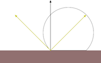 |
 |
 |
| Blinn-Phong | 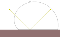 |
 |
 |
|
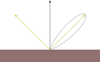
Figure 5: Phong vs Blinn-Phong With Varying Shininess Values. Both the Phong and Blinn-Phong reflectance functions cause a highlight to appear around the direction of reflection. Blinn-Phong has a fix that allows a near-diffuse disctribution at low shininess. Notice that at shininess 1 the Phong highlight would be invisible past 90° from the reflection direction, but Blinn-Phong is visible well past that point. Blinn-Phong also appears slightly more diffuse at all shininess values than Phong. |
|||
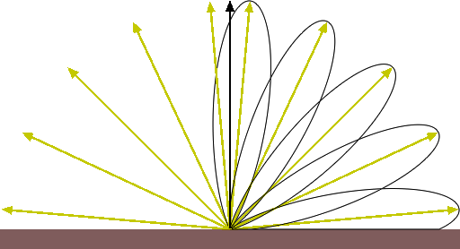
|
| Figure 6: Blinn-Phong at Varying Angles. |
Even if the light does not reach a point on the surface directly, it may reach it by reflecting off of other surfaces in the scene. Rather than compute all the complex interreflections, we approximate this with ambient reflection. The ambient reflection is a simple product of the ambient colors of both the light and material. Direction does not factor in. The ambient reflectance equation is then:
Ia = ma La
Where:
Classic OpenGL also had a color component called emission. It is not strictly part of the Blinn-Phong lighting model, but it has been included in the shader for this week's lab for completeness. Emission is soleley a material property and it represents "glowing" materials. The emission colour is added without modification to the other components.
A vertex shader that implements all of this is included in Demo 2. Its code is shown below:I = Id + Is + Ia + Ie
#version 150

in  vec4 vPosition;
in  vec4 vNormal;

uniform mat4 p;
uniform mat4 mv;
uniform float shininess;
uniform bool lighting;
uniform vec4 ambientProduct;
uniform vec4 diffuseProduct;
uniform vec4 specularProduct;
uniform vec4 emission;
uniform vec4 lightPosition;
uniform vec4 uColor;

out vec4 color;

vec4 mvPosition;

void main()
{

  //Transform the point
  mvPosition = mv*vPosition;  //mvPosition is used often
  gl_Position = p*mvPosition;

  //Set up Normal, Light, Eye and Half vectors
  vec3 N = normalize((mv*vNormal).xyz);
  vec3 L = normalize(lightPosition.xyz - mvPosition.xyz);
  if (lightPosition.w == 0.0) L = normalize(lightPosition.xyz);
  vec3 E = -normalize(mvPosition.xyz);
  vec3 H = normalize(L+E);

  //Calculate diffuse coefficient
  float Kd = max(dot(L,N), 0.0);

  //Calculate Blinn-Phong specular coefficient
  float Ks = pow(max(dot(N,H), 0.0), shininess);

  //Calculate lit colour for this pixel
  color = Kd * diffuseProduct + Ks * specularProduct + ambientProduct + emission;
  if (lighting == false)
	color = uColor;
}
Classic OpenGL has five material properties affect a material's illumination. They are introduced in the Blinn-Phong model section and implemented in the shaders in lab demo 2. They are explained below.
In this week's second demo, L4D2, the five material properties have been declared for you globally, given default values and sent to the shader. They are called MatDiffuse, MatAmbient, MatSpecular, MatShininess, and MatEmission. Corresponding to these five properties are five uniforms in the shader. In the demo program these uniforms have the names DiffuseProduct, AmbientProduct, SpecularProduct, Shininess, and Emission.
Also in this week's second demo the diffuse, ambient and specular material properties are combined with corresponding light properties before being sent to the shader. They could be sent directly to the shader and get combined there, but that would be inefficient. Read chapter 5 of your textbook for an explanation of why. These combined values are called Products in lab demo 2 and in your textbook. Shininess and emission are not affected by light properties and are sent directly to the shader.
In that demo let's specify a light blue diffuse material with a faint, wide white specular highlight, and no emissive property and send it to the shader:
    MatDiffuse = vec4(0.5, 0.7, 1.0, 1);
    MatAmbient = MatDiffuse*0.5;
    MatSpecular = vec4(0.3, 0.3, 0.3, 1);
    MatShininess = 2;
    MatEmission = vec4(0.0f, 0.0f, 0.0f, 1.0f);
    glUniform4fv(DiffuseProduct, 1, MatDiffuse*LightDiffuse);
    glUniform4fv(AmbientProduct, 1, MatAmbient*LightAmbient);
    glUniform4fv(SpecularProduct, 1, MatSpecular*LightSpecular);
    glUniform1f(Shininess, MatShininess);
    glUniform4fv(Emission, 1, MatEmission);
The steps are as follows:
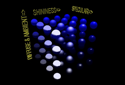
Seeing the effects of varying material properties may help you select the ones you want. In the LIGHTING 1 example pictured below, the program created a 4X4X4 matrix of blue spheres and varied the ambient and diffuse properties along the y-axis, the specular along the x-axis, and the shininess along the z-axis. The values used were as follows:
// set up arrays of various properties
// placed here for convenience
GLfloat materialSpecular[4][4] = {
	{ 0.1f,  0.1f,  0.1f, 1.0f },
	{ 0.33f, 0.33f, 0.33f, 1.0f },
	{ 0.67f, 0.67f, 0.67f, 1.0f },
	{ 0.9f,  0.9f,  0.9f,  1.0f },
};

GLfloat materialAmbDiff[4][4] ={
	{ 0.0f, 0.0f, 0.12f, 1.0f },
	{ 0.0f, 0.0f, 0.25f, 1.0f },
	{ 0.0f, 0.0f, 0.50f, 1.0f },
	{ 0.0f, 0.0f, 1.00f, 1.0f },
};

GLfloat materialShininess[4][1] = {
	{ 0.0f },
	{ 5.0f },
	{ 25.0f },
	{ 125.0f }
};
These values were chosen because they give a relatively even increase in each property as the values change. Figure 7 presents the changes that these properties bring when combined. The color of the spheres are defined by the ambient and diffuse values, and you can see from both the array and the illustration that the colors start off as a very dark blue rise to a bright pure blue. The shininess effect can be observed as the highlight goes from being spread across the entire illuminated hemisphere to a point of light on the surface. If you rotate the matrix about the y-axis, you will see that the highlight disappears when the angles of the reflection no longer hits the viewpoint.
|
| Figure 7: A matrix of spheres showing the range of material properties |
To enable lighting in Core Profile OpenGL you need to write an appropriate shader. The lighting shaders in this week's lab are based on the vertex lighting shaders discussed in Chapter 5 of your textbook. With this shader you can enable and disable lighting by writing GL_TRUE and GL_FALSE to the lighting uniform.
Each individual light source should have color properties, and a position or direction. It may also have other useful properties. The shader for this lab only has one possible light source, but you can extend the idea by creating properties for additional lights.
The light in this week's lab has three colour properties: Diffuse colour, Ambient colour, and Specular colour. The variables for these in the lab code are LightDiffuse, LightAmbient and LightSpecular.
The diffuse component of the light contributes the most to the general reflectance off an object and is what you can consider the "colour" of the light. Shining a light with red diffuse RGBA settings on a white sphere would give a red coloring to all parts of the sphere that the light illuminates.
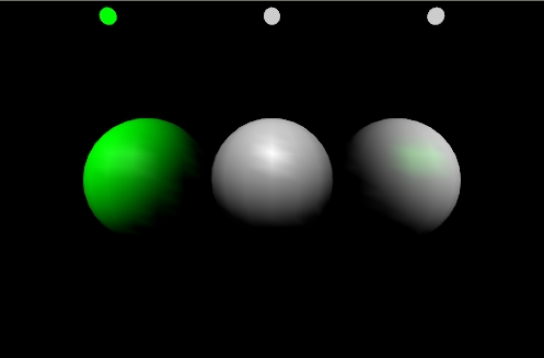
The specular component is the color of the highlights that reflect off a shiny surface. Typically you would set the specular value of a light to be the same as the diffuse value. Figure 8 is a scene from the "LIGHTING 2" program. It shows three white mildly reflective spheres. The sphere in the middle has a light with white diffuse and specular shining on it. The sphere on the left has a green diffuse and white specular light shining on it. The sphere on the right has a white diffuse and a green specular lighting on it.
The variable LightPosition is used to store the position of the light in this week's lab. The variable iLightPosition is bound to the uniform LightPosition in the shader.
If you want the light to be positioned relative to the viewer, simply send that position directly to the shader. If you want to position it somewhere in the world, construct a modelview matrix for it and multiply it against the light's position as you send it to the shader. You could use the current state of the modelview matrix to transform the position of the light in the shader, but then the light would be positioned relative to each individual object rather than appearing to be at one place for the whole frame.
The meaning of LightPosition depends on its fourth or w component. If it is 0.0, the light is treated as a directional source. In this case the light is considered to be infinitely far away in the direction indicated by the LightPosition vector. If the fourth component is not 0.0, it is a positional source. Diffuse and specular lighting calculations are based on the location specified by the x, y and z components of the light in eye coordinates. The default position is (0,0,1,0); thus, the default light source is directional, parallel to, and in the direction of the -z axis.
The following call, if issued before any drawing commands, is equivalent to the default light used in this week's lab:
glUniform4f(iLightPosition, 1, 0.0f, 0.0f, 1.0f, 0.0f);
Attenuation is the reduction in the intensity of the light as the distance increases. Classic OpenGL has three parameters to calculate the attenuation factor: constant, linear, and quadratic attenuation. These three factors are used as shown in this equation:
attenuation = 1.0/(constant + linear * lightDistance + quadratic * lightDistance^2)Attenuation is not implemented in the shaders in this week's lab. This is left for you to do as an exercise.
Lighting equations require normals. These are vectors that indicate what direction a surface is facing. For some figures it is easy to calculate the normal. For example the normal for any point on a sphere can be calculated by subtracting the point's coordinates from the sphere's center point. A cube's normals are simply the unit vectors along the major axes. Other figures have more complicated normals.
If you have two vectors in the plane perpendicular to a surface you can calculate the normal by taking the cross product of those two vectors. For flat sided figures, you can use any two adjacent edges on a face and use their cross product as the normal for all vertices on the face. For smooth figures, you could take the average of the cross products of all neighboring edges that connect to the vertex. If you know the equation that was used to generate the vertices, you could use derivatives of the equation to calculate the normal.
You should always be sure that the normal is of unit length. This is part of the definition. You should normalize the normal after calculating it. You may also need to rescale or normalize the normal after applying modeling or viewing transformations.
Some transformations will cause the angle between the normal and surface to change. Non-uniform scaling is an example of one such transformation. You will need to correct for this. In the case of non-uniform scaling you need to apply the inverse scale to the normal. To this end, you may want to calculate a separate normal matrix to go along with the modelview matrix.
This exercise is broken into two parts:
Goals:
Instructions
/4
Your final submission should not show the torus - it should be black. Place comments near your changes to the code. Make sure your have written answers to 2, 4 and 9.
/6