CS315 Lab 3:
3D Transformations
Highlights of this lab:
This lab is an
introduction to Matrix Transformation
Assignment
After the lab lecture, you have one week to:
- Practice modeling and viewing transformations with boxes.cpp and answer some questions
- Create fingers for a robot arm based on robot_arm.cpp
Use these shaders to help you with your work:
vShaderL3.glsl,
fShaderL3.glsl
Online OpenGL Manual
Lecture Notes
A. The Classic OpenGL Transformation Pipeline
The classic OpenGL pipeline had two main stages of vertex transformation, each with its own transformation matrix. These were built into the graphics hardware. These days, other transformation pipelines have become possible since transformations are done in the vertex shader. However, in this lab, as in the textbook, we will try to implement the classic pipeline.
Each vertex in the scene passes
through two main stages of transformations:
- Model view transformation (translation, rotation, and
scaling of objects, 3D viewing transformation)
- Projection (perspective or orthographic)
There is one global matrix
internally for each of the two stage above:
Given a 3D vertex of a polygon, P =
[x, y, z, 1]T, in homogeneous coordinates, applying the model view
transformation matrix to it will yield a vertex in eye relative coordinates:
P’ = [x’, y’, z’, 1]T =
Mmodelview*P.
By applying projection to P’, a 2D
coordinate in homogeneous form is produced:
P” = [x”, y”, 1]T =
Mprojection*P’.
The final coordinate [x”, y”] is in a normalized coordinate form and can be easily mapped to a location on the screen to be drawn.
Setting Up The Modelview and Projection Matrices in your shader
Since OpenGL Core Profile always uses shaders, neither the
modelview nor the projection matrix is available. You have to set them
up yourself. The matrices will be allocated and given their values in
the main program, and they will be applied to vertices in the shader
program.
To help us create and manipulate matrices in our main program we
will use the matrix classes and helper functions in mat.h
. Each matrix will be initialized to identity if you use the
default constructor. So to create our initial modelview and projection
matrices we would declare two mat4 objects like so:
mat4 mv;   // create a modelview matrix and set it to the identity matrix.
mat4 p;    // create a projection matrix and set it to the identity matrix.
These two matrices can be modified either by assigning or post-multiplying
transformation matrices on to them like this:
p  = Perspective(45.0f, aspect, 0.1f, 10.0f); // Set the projection matrix to
                                              // a perspective transformation

mv *= RotateY(45); // Rotate the modelview matrix by 45 degrees around the Y axis.
As in this example, we will usually
set the projection matrix p by assignment, and accumulate transformations in the modelview matrix mv by post multiplying.
You will use uniforms to send your transformations to the vertex shader and apply them to
incoming vertices. Last lab you did this for colours by making vector type uniforms. Uniforms can also be simple values and matrices.
// other shader value declarations
uniform mat4 mv; //declare modelview matrix in shader
uniform mat4 p;  //declare projection matrix in shader

void main()
{
  //other shader code

  //apply transformations to incoming points (vPosition)
  gl_Position = p * mv * vPosition;

  //other shader code
}
To set the value of uniform shader variables you must first request their index like this:
//Global matrix variables
GLint projIndex;
GLint mvIndex;


//In your init code
// Get location of projection matrix in shader
projIndex = glGetUniformLocation(program, "p");

// Get location of modelview matrix in shader
mvIndex = glGetUniformLocation(program, "mv");
Then, you use a glUniform*
function with the index and a local variable to set their value. Do
this whenever you need to update a matrix - usually when the window is resized or right before you draw something. To set the value of our 4x4
float type matrices we will use the form glUniformMatrix4fv:
//in display routing, after applying transformations to mv
//and before drawing a new object:
glUniformMatrix4fv(mvIndex, 1, GL_TRUE, mv); // copy mv to uniform value in shader

//in reshape, after calculating a new projection matrix
//or as needed to achieve special effects
glUniformMatrix4fv(projIndex, 1, GL_TRUE, p); // copy p to uniform value in shader
B. Elementary Transformations
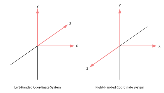
- Right-handed and left-handed coordinate
system: With your right hand line your first two fingers
up with the positive y axis and line your thumb up with the
positive x axis. When you bend your remaining two fingers, the
direction they point is the positive z axis in a right handed
coordinate system. Compare to the figure below. The other system
shown is a left-handed coordinate system. It is sometimes used in
graphics texts. A consequence of using the right-handed system is
that the negative z-axis goes into the screen instead of the positive as you might expect.
- Right-handed coordinate
system is used most often. In OpenGL, both the local coordinate system for
object models (such as cube, sphere), and the camera coordinate system are
use a right-handed system.
- In the following discussion, we assume that all transformation
function calls return a matrix that you will post-multiply onto
Mmodelview, unless the other is specifically
mentioned.
- All transformation functions in this discussion that do not begin
with gl are equivalent or similar to a classic OpenGL
transformation function and are defined in mat.h. They
all use the float data type for simple values.
Translation:
Translate(dx, dy, dz);
Where [dx, dy, dz] is the translation vector.
The effect of calling this function is to create the translation
matrix defined by the parameters [dx, dy, dz] which you should concatenate to the global model view matrix:
Mmodelview = Mmodelview * T(dx, dy, dz);
Where T(dx, dy, dz) =
In general, a new transformation matrix is always concatenated to
the global matrix from the right. This is often called
post-multiplication.
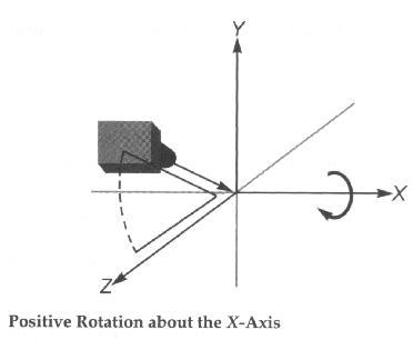
Rotation:
Rotate*(angle)
Where angle is the angle of counterclockwise rotation in
degrees, and * is one of X, Y or Z.
Classic OpenGL defined a rotation function capable of rotating
about an arbitrary vector. However, typically we rotate about only one
of the major axes, which simplifies x, y and z to be a
unit vector. These simple rotations were then concatenated to produce
the arbitrary rotation desired. Because of this mat.h
provides functions that only produce the simplified x, y and z
rotation matrices.
The effect of calling a rotation matrix is similar to
translation. For example, the function call:
RotateX(a);
and concatenating it to the global modelview matrix will have the following effect:
Mmodelview = Mmodelview *
Rx(a);
Where
Rx(a) denotes the rotation matrix about the x-axis for degree
a: Rx(a) = 
Rotation matrices for the y-axis or z-axis can be achieved respectively
by these functions calls:
RotateY(a) // rotation about the y-axis
RotateZ(a) // rotation about the z-axis
Scaling
Scale(sx, sy, sz);
where sx, sy and sz are the scaling factors along
each axis with respect to the local coordinate system of the
model. The scaling transformation allows a transformation matrix to change
the dimensions of an object by shrinking or stretching along the major
axes centered on the origin.
Example:
to make the wire cube in this week's sample code three times as high, we can stretch it along the y-axis
by a factor of 3 by using the following commands.
     // make the y dimension 3 times larger
     mv = mv * Scale(1, 3, 1);
     glUniformMatrix4fv(mvIndex, 1, GL_TRUE, mv);
     // draw the cube
     glDrawArrays(GL_LINE_STRIP, wireCubeStart, wireCubeVertices);
- It should be noted that the scaling is always about the origin
along each dimension with the respective scaling factors. This means
that if the object being scaled does not overlap the origin, it will
move farther away if it is scaled up, and closer if it is scaled
down.
- The effect of concatenating the resulting matrix to the global model
view matrix is similar to translation and rotation.
C. The Order of Transformations
- When you post-multiply transformations as we are doing and as is
done in classic OpenGL, the order in which the transformations are
applied is the opposite of the order in which they appear in the
program. In other words, the last transformation specified is the
first one applied. This property is illustrated by the following
examples.
- The initial default position for the camera is at the
origin, and the lens is looking into the negative z direction.
- Most object models, such as cubes or spheres, are also defined at
the origin with a unit size by default.
- The purpose of model view transformation is to allow a user to
re-orient and re-size these objects and place them at any desired
location, and to simplify positioning them relative to one another.
Example:
Suppose we want to rotate a cube 30 degrees and place it 5 units
away from the camera for drawing. You might write the program
intuitively as below:
    // first rotate about the x axis by 30 degrees
    mv *= RotateX(30);

    // then translate back 5
    mv *= Translate(0, 0, -5);

    // Copy mv to the shader
    glUniformMatrix4fv(mvIndex, 1, GL_TRUE, mv);

    // Draw a cube modelcentered at the origin
    glDrawArrays(GL_LINE_STRIP, wireCubeStart, wireCubeVertices);
The following figure shows the effect of these transforms:
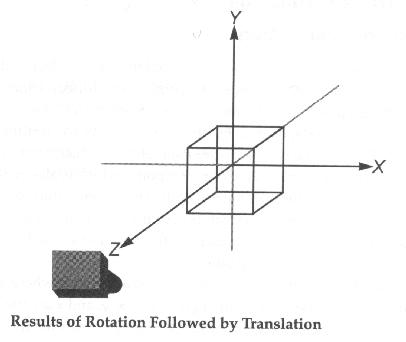
If you run this program, you might be surprised to find that
nothing appears in the picture! Think about WHY.
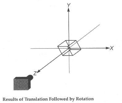
If we modify the program slightly as below:
    // first translate back 5
    mv *= Translate(0, 0, -5);

    // then rotate about the x axis by 30 degrees
    mv *= RotateX(30);

    // Copy mv to the shader
    glUniformMatrix4fv(mvIndex, 1, GL_TRUE, mv);

    // Draw a cube modelcentered at the origin
    glDrawArrays(GL_LINE_STRIP, wireCubeStart, wireCubeVertices);
The following figure shows the new result:
D. Modeling Transformation vs.
Viewing Transformation
- OpenGL
uses concepts of a modeling transformation and a viewing transformation.
- The modeling transformation is the product of the calculations for creating and
laying out your model (making sure everything is correctly positioned and oriented
relative to everything else in the model). The transformation functions
Scale(), Rotate*() and Translate()
can be used to alter the modeling matrix.
- The viewing transformation is the sequence of
calculations for viewing the model (positioning the viewpoint so
that you view the model from the orientation and position you
desire). You could also use the combination of Scale(),
Rotate*() and Translate() for viewing
transformations. The following discussion explains how this
approach works. However, it involves the concepts of local and
global coordinates and could be very confusing to some
students. I would like to suggest students to skip this part
first (notice I labeled it OPTIONAL), and proceed with the
easy approach, LookAt(), discussed next.
OPTIONAL
- First let's look at the following code:
    mv *= Translate(0, 0, -5);
    mv *= RotateY(30);
    DrawTheModel();
Working down to the model's local coordinate system, we
first move the local origin down the negative z-axis by 5
units and then rotate that coordinate system about the y-axis by 30
degrees.
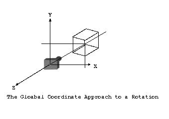
Working up to the global coordinate system from the model,
we first rotate the coordinate system about its origin by -30 degrees,
then move it's origin down the positive z-axis by 5 units. The model
is fixed, but the global coordinate system is rotated and
translated. The viewpoint locates at the origin of the global
coordinate system. Remember that in the global coordinate approach,
the order is reversed, and the orientation order is also reversed.
The following picture illustrates the local approach to a rotation:
The following picture illustrates the global approach to a rotation:
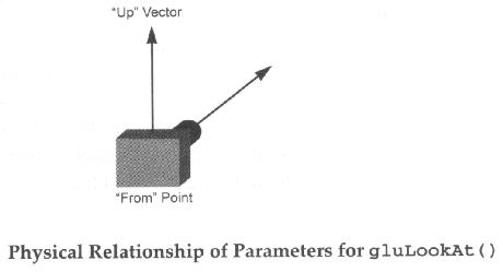
The LookAt() Function:
define a viewing transformation
void LookAt( GLfloat eyex,    GLfloat eyey,    GLfloat eyez,
             GLfloat centerx, GLfloat centery, GLfloat centerz,
             GLfloat upx,     GLfloat upy,     GLfloat upz )

or

void LookAt (vec4 eye, vec4 center, vec4 up)
Parameters
  eye    or eyex,    eyey,    eyez:    specifies the position of the eye point;
  center or centerx, centery, centerz: specifies the position of the reference point;
  up     or upx,     upy,     upz:     specifies the direction of the up vector.
The LookAt() function makes it easy to move both the
"from" and the "to" points in a linear manner. For
example, if you need to pan along the wall of a building located away
from the origin and aligned along no axes in particular, you could
simply take the "to" point to be one corner of the building
and calculate the "from" as a constant distance from the
"to" point. To pan along the building, just vary the
"to" point.
E. Saving and Restoring the Matrix
- Whichever method you use, you will almost always need to either reset the matrix to the identity matrix, or save and restore a previous matrix state. To reset to the identity matrix use code like this:
mv = mat4(); //restore mv to the identity matrix
To save and restore a matrix you need to use a matrix stack. Classic OpenGL had one built in, but it is missing from Core Profile, so use this class from Dr. Angel's textbook and sample code instead:
Add near top of your .cpp file
//This include is required to use assert function call.
#include <cassert>

// Dr. Angel's matrix stack - used to simulate classic OpenGL push and pop
class MatrixStack {
    int _index, _size;
    mat4* _matrices;
public:
   MatrixStack (int numMatrices = 32):_index(0), _size(numMatrices)
    {_matrices = new mat4[numMatrices];}

    ~MatrixStack ()
    {delete[] _matrices;}

    void push(const mat4 &m)
    {assert (_index + 1 < _size);
    _matrices[_index++] = m;}

    mat4& pop(void)
    {assert (_index - 1 >= 0);
    return _matrices[--_index];}
};
To use it, write code like this:
Add to your global variables
//global modelview matrix stack
MatrixStack matStack;
In display, use .push() and .pop() around transforms that you only want to affect one or a limited set of objects.
matStack.push(mv);

//Apply transforms to modelview matrix
//Draw objects
//... etc ...

//restore old modelview matrix
mv = matStack.pop();
You can store any mat4 matrix on the matrix stack so long as you remember to pop back to the correct matrices in the correct sequence.
F. Viewport and Projection Transformations
- Once you have learned Modelview transformations, the next step is
to understand projection modes and viewport mapping.
Viewport Transformation
The glViewport() function takes four parameters, which
are used to specify the lower-left corner coordinates and the width
and height of the viewport, or the drawable area in your OpenGL
view. It is best to call it only once you know how big the window
is. That means it should be in your rehape function.
Projection Transformation
OpenGL provides two methods of converting 3D images into 2D ones.
- The first is orthographic, or parallel
projection. You use this style of projection to maintain the scale of objects
and their angles without regard to their apparent distance.
- The second is Perspective projection. This is the most
popular choice in 3D graphics. OpenGL's perspective projection is
created by a couple of commands in mat.h, Frustum() and Perspective().
Projection is handled by the MProjection matrix. You do not usually concatenate to the projection matrix as you do with the modelview matrix.
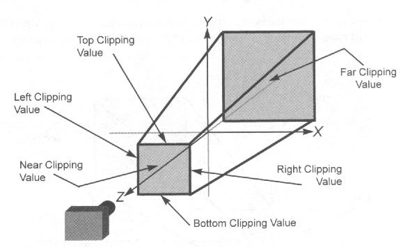
glFrustum()
  void Frustum( GLfloat left, GLfloat right,
                GLfloat bottom, GLfloat top,
                GLfloat near, GLfloat far )

  Parameters:
     left, right:
         Specify the coordinates for the left and right vertical
         clipping planes;
     bottom, top:
         Specify the coordinates for the bottom and top horizontal
         clipping planes;
     near, far:
         Specify the distances to the near and far depth
         clipping planes.  Both distances must be positive.
Frustum() describes a perspective matrix that
produces a perspective projection. (left, bottom, -near) and (right,
top, -near) specify the points on the near clipping plane that are
mapped to the lower left and upper right corners of the window,
respectively, assuming that the eye is located at (0, 0, 0). -far
specifies the location of the far clipping plane. Both near and far
must be positive.
The following shows perspective viewing volume and the Frustum()
parameters
Perspective()
Although Frustum() is powerful, it is not very
intuitive. There is a much simpler perspective command, called
Perspective(). Like Frustum() it generates a
perspective viewing volume but only a simple one. It lacks the
flexibility of Frustum which can be manipulated to achieve
special effects.
  void Perspective( GLfloat fovy, GLfloat aspect,
                    GLfloat zNear, GLfloat zFar )

  Parameters:
      Fovy:

          Specifies the field of view angle, in degrees, in the y
          direction;

      Aspect:

          Specifies the aspect ratio that determines the field of view in
          the x direction.  The aspect ratio is the ratio of x (width) to
          y (height);

      ZNear:

          Specifies the distance from the viewer to the near clipping
          plane (always positive);

      ZFar:

          Specifies the distance from the viewer to the far clipping
          plane (always positive).
Perspective() specifies a viewing frustum into the world
coordinate system. In general, the aspect ratio in Perspective
should match the aspect ratio of the associated viewport. For example,
aspect=2.0 means the viewer's angle of view is twice as wide in x as
it is in y. If the viewport is twice as wide as it is tall, it
displays the image without distortion.
The following shows perspective
viewing volume and the Perspective() parameters
Assignment
Goals of this assignment:
- Viewing Transformations: through LookAt or equivalent modeling transformations
- Projection Transformations: through Frustum, Perspective, and Ortho
- Modeling Transformations: rotation, translation, scaling, matrix push and pop
Part 1
Start with this code: boxes.cpp and this lab's shaders:
vShaderL3.glsl,
fShaderL3.glsl.
As written, this program draws a basic coordinate system with a green x-axis, a red y-axis, and a blue z-axis. These will be referred to in the instructions as the axes
With the initial camera settings you are looking directly down the z-axis so you will not see it.
Make the following changes. Write your answers to the questions in steps 1, 2, 4 and 11.
-
Comment out the LookAt() call and replace it with a Translate() with parameters ( 0.0f, 0.0f, -5.0f )
Is there any change in the display? Why? Why not?
-
Comment out both the LookAt() and Translate() lines. What happens? Why?
-
Restore the LookAt() call.
-
Comment out the Frustum() call and replace it with an equivalent Perspective() call. You may have to do some trigonometry to figure out the field of view. You should already know how to calculate the aspect ratio.
- What is the original field of view angle? What happens when you change it to
30.0? Why?
- The original aspect ratio is 1.0. What happens when you modify the aspect ratio to values higher or lower than 1.0?
- Restore the original Frustum() call. (Commenting out the Perspective() call)
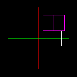
- Draw a wirecube centered at (0, 0, 0) relative to the axes. You
can use the provided VAO and related constants. Do this in the "display" function.
- Move this cube so that it is centered at (1, 0, 0) relative to the axes.
- Draw a second cube after the first - in a new colour if you can - and rotate it 45 degrees around the y-axis.
- Place this rotated cube directly above the first cube. It will be centered at (1, 1, 0) relative to the axes. Be careful of the order of transformations.
-
The perspective view makes the two cubes look a little awkward. Try
using orthographic projection instead of the Frustum
call. The function for that is: Ortho (the arguments are
similar to Frustum, but you may want to send it larger
left, right, bottom, and top values). See the picture for expected
results:
Please leave commented Perspective and Frustum calls in your program.
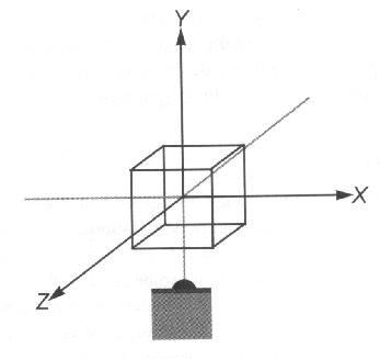
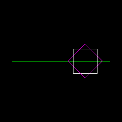
-
Rotate everything (using modeling transformations NOT LookAt) so that you
are looking down at the top of the boxes
and seeing the blue z-axis (and no red y-axis). See the picture for expected results:
If you wanted to leave your x and y axes unchanged, but still see the top of
the boxes, like this:
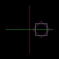
how would
you change your code?
-
Rotate everything so that you can see all three axes along with the
two cubes. See the picture for expected results:
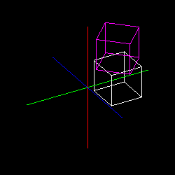
You may use different angles of course.
/5 marks
Part 2
Start with this code with a simple arm and use this lab's shaders:
vShaderL3.glsl,
fShaderL3.glsl.
- First build the program and see how it works. Try pressing lower and
uppercase 'e' to move the elbow. Try pressing lower and uppercase 's' to
move the shoulder
- Now, add three fingers and a thumb to the robot.
Use matStack.push() and matStack.pop() to separate the transformations for each digit. Do not attempt to "untransform" with an inverse rotate, translate or scale.
- Finally, add some code that will make the finger and thumb move apart
when 'f' is pressed and and together when 'F' is pressed. The center of rotation should be at the wrist.
Your completed robot hand might look something like the following.
If you have a WebGL capable browser, you can interact with this arm. Click on it and use the keys described. I have also added r/R to rotate the arm on the X axis so you can see it from above, and t/T button to switch between solid and wire cubes.
/5 marks
Deliverables
- Part 1
- A working version of the program.
A single .cpp file will suffice. Please provide your shaders if you modified them.
- Document with written answers for the questions in Steps 1, 2, 4, and 11.
- Part 2
- A working version of the robot arm program. A single .cpp file will suffice. Please provide your shaders if you modified them.
On-Line References
- Robot Arm Exercise: Neider, Jackie (1997) OpenGL Redbook, Chapter 3, USA: A-W Developers Press.
- Selected pictures: Fosner, Ron (1997) OpenGL Programming for Windows 95 and Windows NT, USA: Addison-Wesley books.