This lab is an introduction to Fundamental OpenGL Functions
After the lab lecture, you have one week to:
Before you begin this seminar, create a new project like you did in the first lab, but don't add the two shader files or change anything in the basic GLUT program. You will complete the project by following the instructions in this lab's notes instead.
OpenGL is an operating system and hardware platform independent
graphics library designed to be easily portable yet rapidly executable.
Unlike Direct3D, which is only available on PC, Xbox 360 and Windows
Mobile OS, OpenGL is available on a wide variety of hardware platforms
and operating systems including Unix/X11 (Linux, Irix, BSD, Solaris),
Mac OS X, and Microsoft Windows 98 to Windows 8. The embedded version,
OpenGL ES, is available on many hand held devices including iPhone OS
and Android OS devices. A Javascript version of OpenGL ES 2.0 called
WebGL is an official part of the HTML 5 specification.
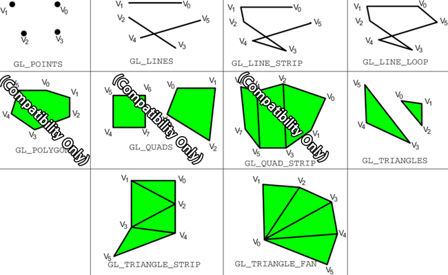
Your graphics hardware has limited ability to represent geometry. Most hardware only understands triangle rendering primitives. Everything else is built up using triangles. Older versions of OpenGL included some other shapes that were supported by some specialized hardware, such as convex polygons and quadrilaterals, but that support was removed in Core profile. Below is a diagram showing OpenGLs different primitive types or modes:
Drawing with one of these types is controlled by a glDrawArrays
function. The glDrawArrays
function tells your rendering context to
begin drawing a certain number of elements from a list of vertex data
that has already been loaded into an array buffer object and connected
to appropriate shader inputs. So, to be able to draw you will need to
know how to load vertex data into a buffer, and how to attach it to a
shader. Eventually you will also learn how to quickly switch between
buffers of drawable
objects with Vertex Array Objects (VAOs)
Before you can do any drawing you need to tell OpenGL what to do with the things you tell it to draw. You do this with shader programs. OpenGL 3.2 Core Profile uses GLSL 1.5 as its shader programming language. Shader programs consist of a minimum of two parts: a vertex shader and a fragment shader.
You may also have heard of two other shader types: geometry shaders and tesselation shaders. Geometry shaders were introduced in OpenGL 3.2 Core Profile and tesselation shaders were introduced in OpenGL 4.0. They are optional and will not be covered in these labs.
You will send lists of vertex information into a vertex shader. This information comes in through variables labelled with the in modifier. This information represents attributes of the vertex that can change from one vertex to the next such as colour and position. Vertex shader inputs are also known as attributes.
When we are done manipulating and creating shader properties, we pass the results along to the fragment shader through outputs labelled with the out modifier. If the vertex shader outputs are different for the vertices in the same primitive, they will be interpolated across the primitive - their values will vary. Vertex shader inputs are also known as varyings.
Below is our first vertex shader: Add a new file called vshader.glsl to your project and paste in the vertex shader code:
#version 150

in  vec2 vPosition; //receives incoming vertex positions
out vec4 colour;    //passes the colour of this vertex to the fragment shader

void main()
{
  //Add default z and w coordinates to the incoming position and pass it on.
  gl_Position = vec4(vPosition, 0.0, 1.0);

  //Colour every vertex red
  colour = vec4(1.0, 0.0, 0.0, 1.0); //colour channes are red, green, blue and alpha
}
This vertex shader only has one input which represents a 2D coordinate for the vertex. This coordinate is in a 2 component vector which has a base type of float, a 32-bit IEEE floating point value. Vertices can be moved around in space, coloured, and lit by the vertex shader. You will explore many of these things later. For now, our vertex program will only provide a colour for the vertex. This colour is hard coded and will be the same for all vertices. You will learn how to change this colour programmatically later on.
Our first vertex shader has two outputs as well. You can see the declaration for a 4 component vector, vec4, for colour, and we use the built-in output gl_Position, which is also a vec4, which is why the shader adds two more components to vPosition when we assign it to gl_Position.
The fragment shader gets data that is blended from each vertex that makes up the primitive being drawn. This could be a position somewhere between each vertex, a texture lookup coordinate, or a blended colour. For now our shader will ignore gl_FragCoord, the fragment position, and simply copy the incoming colour to the screen.
Add a new file called fshader.glsl to your project and paste in the vertex shader that matches your computer's capabilities:
#version 150

in  vec4 colour; //The blended fragment colour from the vertex shader.
                 //Name must match an output in the vertex shader.
out vec4 fragColour; //Define a name for the colour output

void main()
{
    fragColour = colour;
}
This fragment has one input for the interpolated colour. It is important that names for the inputs you create in a fragment shader match the name of an output you create in the vertex shader.
There is no built-in output for fragment colour in GLSL 1.5, so we create one ourselves. There used to be one called gl_FragColour in GLSL 1.2. The name chosen here reflects the old name, but it could be anything.
    // Load and compile shaders, then use the resulting shader program
    GLuint program = InitShader( "vshader.glsl", "fshader.glsl" );
    glUseProgram( program );
Basic OpenGL rendering primitives are made up of
lists of vertices.
Vertex data can be two, three of four dimensional. An extra dimension
is sometimes necessary to properly move vertices around in space.
Vertex data is most often represented with the vec2, vec3, and vec4 data types in
the shader. These are 2, 3 and 4 component floating point structures.
You should represent this data with arrays of the GLfloat data type in
your program. For example, the following 2 dimensional array gives the 2D coordinates
for the three vertices in a triangle:
//Triangle positions
GLfloat points[3][2] =
{
	{ 0.9f,  0.9f},
	{ 0.9f,  0.0f},
	{ 0.0f,  0.9f}
};
The number of coordinates provided per vertex
should match the vec
type specified on the position input of the shader you are using.
Dr. Angel's OpenGL framework defines C++ classes for the vec2, vec3 and vec4 data types. The following code is identical to to the array above, but uses the vec2 class:
//Triangle positions
vec2 points[] =
{
	vec2( 0.9f,  0.9f),
	vec2( 0.9f,  0.0f),
	vec2( 0.0f,  0.9f)
};
You can use either form interchangeably, but I prefer to use Dr. Angel's vec* classes because they provide many convenient features that are hard to reproduce with simple arrays.
Once you have some vertex data, you need to load it into buffers. Each array can be loaded into a separate buffer, or all the arrays can be packed into the same buffer. You will find examples of both in various code samples in your textbook. For now, we will use separate buffers for position and colour data.
To create a buffer, you use the glGenBuffers
command. glGenBuffers() creates valid buffer names which you
must bind to work with and load with buffer data.
void glGenBuffers(GLsizei  n,  GLuint *
buffers);
Where n specifies how many names to generate, and buffers is a reference to enough memory for the n names.
Once you have a buffer name, you bind it with glBindBuffer.
A buffer is not allocated until you bind it the first time.
void glBindBuffer(GLenum target, GLuint buffer);Where target indicates what type of data the buffer holds, and buffer is a valid buffer name generated with glGenBuffers().
You will use the target type GL_ARRAY_BUFFER for storing all vertex data in these labs.
With the buffer bound, you are ready to load data into it with glBufferData.
void glBufferData(GLenum  target,
GLsizeiptr  size,  const GLvoid *  data,
GLenum  usage);
Where:
- target indicates what type of data you are sending (you will always use GL_ARRAY_BUFFER),
- size is the size of the incoming data in bytes,
- data is a pointer to the start of your data array,
- usage indicates how the data will be used.
Since you will likely use your buffers for drawing simple geometric objects, you will generally specify the GL_STATIC_DRAW usage type. If you plan to update the buffer frequently, you might want to specify GL_DYNAMIC_DRAW. If you plan to use the buffer infrequently you should specify GL_STREAM_DRAW. A buffer's data may be updated with another call to glBufferData(). If you plan to update only a portion of a buffer's data, consider using glBufferSubData.
Here is how we would load our sample triangle position data. Since we will only load the data once, place this code in init after the shader loading code:
    //*** Position buffer **********************
    // Create a buffer for vertex positions, make it active, and copy data to it
    GLuint positionBuffer;
    glGenBuffers( 1, &positionBuffer );
    glBindBuffer( GL_ARRAY_BUFFER, positionBuffer );
    glBufferData( GL_ARRAY_BUFFER, sizeof(points), points, GL_STATIC_DRAW );
glBufferData( GL_ARRAY_BUFFER, 3*sizeof(vec2), points, GL_STATIC_DRAW );
First, though, you need a vertex array object. Vertex array objects, or VAOs, manage the connections between buffers and your shader. If you want to have multiple sets of buffers each describing separate objects, you can quickly switch between them by using one VAO for each. You configure them with the connections, then just before drawing you bind the one that you want and it switches what you will draw.
For now we will make only one VAO. You may see that some of the labs use multiple VAOs.
To create a VAO, you use the glGenVertexArrays command. I works a lot like glGenBuffers
void glGenVertexArrays(GLsizei n, GLuint *arrays);Where n specifies how many arrays to generate, and buffers is a reference to enough memory for the n names.
To make it active and ready to configure or draw with, you use glBindVertexArray
void glBindVertexArray(GLuint array);Where array is a valid array name generated with glGenVertexArrays
Here is how you would set up your vertex array to manage buffer/shader connections. It is important that your vertex array appear before the glVertexAttribPointer function. Dr. Angel seems to prefer to place it before generating buffers, so put it there.
    //*** Vertex Array Object ******************
    GLuint vao;
    glGenVertexArrays(1, &vao);
    glBindVertexArray(vao);
Now we're ready to connect the buffers to the shader inputs.
To get a reference to a shader input you use glGetAttribLocation.
GLint glGetAttribLocation(GLuint program, const GLchar * name);Where program is a valid, compiled shader program, and name is a character string containing the name of the desired shader input.
If name does not refer to a valid input in the specified shader program, the returned result will be -1.
To enable the shader input you use glEnableVertexAttribArray.
void glEnableVertexAttribArray(GLuint index);Where index is a value returned from glGetAttribLocation.
To attach the currently bound buffer to a shader input you use glVertexAttribPointer.
void glVertexAttribPointer(GLuint index, GLint size, GLenum type, GLboolean normalized, GLsizei stride, const GLvoid * pointer);Where:
- index is a value returned from glGetAttribLocation.
- size is the number of components being sent per vertex. Must be 1, 2, 3, or 4.
- type is the data type of the components. You will be using GL_FLOAT.
- normalized is for fixed point data and doesn't apply to the type GL_FLOAT. Use GL_FALSE.
- stride indicates the number of bytes between values that apply to this shader input. This allows us to send interleaved data. If your values are tightly packed, use 0 as your argument.
- pointer is the offset of the first relevant component in your buffer. If you are using separate buffers for each vertex attribute (color, position, texture coordinate, etc), this should be 0.
- Notice that this is a void, or untyped, pointer. OpenGL is a C library that doesn't support polymorphism. A void pointer is a C programming mechanism that is sometimes used to pass data of different types to a function. The type is usually stated by one of the arguments to the function. Here the type is specified with the type argument.
The purpose of the size and type arguments is to describe the data being sent to the shader. If the original data doesn't match what's asked for in the shader, it will converted for you. In fact, all vertex attributes are converted to size 4. If y or z are missing, they become 0, and if w is missing it becomes 1. You can then define an in in the shader of a different size depending on your need.
Here is how we will attach the sample triangle position buffer to the "vPosition" input of the shader:
    //Enable the shader's vertex position input and attach the active buffer
    GLuint vPosition = glGetAttribLocation( program, "vPosition" );
    glEnableVertexAttribArray( vPosition );
    glVertexAttribPointer( vPosition, 2, GL_FLOAT, GL_FALSE, 0, 0 );
Finally, to draw things, use glDrawArrays.
To draw the sample triangle place this code in the draw function before the glutSwapBuffers command:
void glDrawArrays(GLenum mode, GLint first, GLsizei count);Where:
- mode is what primitive to draw with
- first is what vertex to start at in the array you loaded
- count is how many vertices to draw.
    glClear( GL_COLOR_BUFFER_BIT );
    glDrawArrays( GL_TRIANGLES, 0, 3 );
If you have done everything to this point you should see a red
triangle in the upper right corner of an otherwise black rendering
window. Now its time to experiment with different drawing modes.
draws a point for each vertex
Three different line primitives can be created:
Some OpenGL implementations let you control the width of lines with glLineWidth(). On most Macs, the range of line widths is 1.0 to 1.0, which is the minimum defined in the standard. You may find that your PC allows more.
Try this points array with each of the above triangle types:
//TriangleIt may be hard to see why you get the results you observe. Consider the order the points are defined and how triangles are defined for each triangle type. If you are still confused, try using glPolygonMode to switch to outline mode rather than fill mode.
vec2 points[] =
{
vec2( 0.0f, 0.0f ),
vec2( 0.5f, 0.0f ),
vec2( 0.5f, 0.5f ),
vec2(-0.5f, 0.5f ),
vec2(-1.0f, 0.0f ),
vec2(-0.5f,-0.5f )
};
So far our shader has used a hard coded colour. You can change this colour in a running program in one of two ways: uniform colours, and colour arrays. These are explained below.
All our colours will be in RGBA format - Red, Green,
Blue, Alpha. Alpha is an extra term used in blending operations. You can think of it as "transparency", but it can do more than that. The alpha channel will be ignored in our programs this week.
In your shader code, a uniform is declared next to other inputs like this:
uniform type uniformName;

//eg: a 4 component colour uniform
uniform vec4 uColour; //copy this to your colour output
You get access to a uniform in much the same way as a vertex array input, but you use glGetUniformLocation:
GLint uniformLocation = glGetUniformLocation(shaderProgram, "uniformName");You change the value of a uniform with glUniform*() type functions. The * represents the format of the uniform you are changing and has two or three parts:
//eg: get the colour from the example above for use in lab sample code
GLint uColour; //Getting uniforms can be slow. Make this global?
uColour = glGetUniformLocation(program, "uColour");
   glUniform4f( uColour, 1.0f, 1.0f, 0.0f, 1.0f ); //Yellow

   GLfloat yellow[4] = { 1.0f, 1.0f, 0.0f, 1.0f }; //Yellow
   glUniform4fv( uColour, 1, yellow);
These work just like vertex position arrays. You will need to set up a second array input to your vertex shader, create a colour array, load it into a buffer and attach it to your shader. Here are samples of all three:
The following code defines an attribute input called vColour. It is similar to the code used for vPosition. You should assign the value in vColour to the colour output:
in vec4 vColour; // Per vertex colour input
//for initial triangle
vec4 colours[] =
{
	vec4(1.0f, 0.0f, 0.0f, 1.0f), //Red
	vec4(0.0f, 1.0f, 0.0f, 1.0f), //Green
	vec4(0.0f, 0.0f, 1.0f, 1.0f), //Blue
};

//for later triangle types example
vec4 colours[] =
{
	vec4(1.0f, 0.0f, 0.0f, 1.0f), //Red
	vec4(0.0f, 1.0f, 0.0f, 1.0f), //Green
	vec4(0.0f, 0.0f, 1.0f, 1.0f), //Blue
	vec4(1.0f, 1.0f, 0.0f, 1.0f), //Yellow
	vec4(0.0f, 1.0f, 1.0f, 1.0f), //Cyan
	vec4(1.0f, 0.0f, 1.0f, 1.0f), //Magenta
};
Then copy the colour data to a buffer, like this:
    //*** Colour buffer **********************
    // Create a buffer for colour positions, make it active, and copy data to it
    GLuint colourBuffer;
    glGenBuffers( 1, &colourBuffer );
    glBindBuffer( GL_ARRAY_BUFFER, colourBuffer );
    glBufferData( GL_ARRAY_BUFFER, sizeof(colours), colours, GL_STATIC_DRAW );


    //Enable the shader's vertex colour input and attach the active buffer
    GLuint vColour = glGetAttribLocation( program, "vColour" );
    glEnableVertexAttribArray( vColour );
    glVertexAttribPointer( vColour, 4, GL_FLOAT, GL_FALSE, 0, 0 );
The process is very similar to the position buffer set up. I have highlighted the differences in red.
The colour buffer and depth buffer are usually cleared each time you begin drawing to the OpenGL window. The values you use to clear with rarely change, so they are often set in the initialisation step with the glClearColor and glClearDepth functions:
glClearColor(0.0f, 0.0f, 0.0f, 1.0f ); //clear colour is blackThe actual clearing happens just before you draw. In your main draw routine, you specify which buffers to clear with the glClear function:
glClearDepth(1.0f); //Clear to maximum distance
glClear(GL_COLOR_BUFFER_BIT | GL_DEPTH_BUFFER_BIT);
In this lab you will be drawing 2D objects. When you draw in 2D (or you are doing 3D CAD work) you should use a special geometry transformation that does not cause shape or size distortion. This transformation is called orthographic projection. In the last lab we wanted a 3D effect with foreshortening so we used perspective projection. Perspective transformation makes it hard to place things precisely on the screen. Shapes are distorted toward the edges and corners, and their apparent size varies with their distance from the camera. With orthographic projection you can precisely control how coordinates map to the drawing area, and objects render the same way regardless of distance.
This week, we will use only simple normalized device coordinates - our
drawing space will lie between (-1,-1) in the lower left corner and (1,1) in
the upper right. If you are using 3D coordinates, then -1 is the nearest
possible Z coordinate, and 1 is the farthest. Things do not appear smaller with distance. Next week, when you learn to do
perspective projection and other transformations, you will also see Dr.
Angel's
Ortho() or glOrtho2D()
functions which give you control over how coordinates are
mapped to the window when you don't do perspective.
In the last two sections we've discussed how to clear the depth buffer, and the default range of depth values. Perhaps you'd also like to know how to specify 3D vertices and do depth testing.
Without depth testing, objects appear on the screen in the order you draw them. If you want to draw something behind another thing you have already drawn, you need to turn on depth testing, supply depth values with your vertex coordinates, and clear the depth buffer each time you start drawing.
In more detail:
glEnable(GL_DEPTH_TEST);
//Triangle
vec3 points[] =
{
   vec3( 0.0f, 0.0f,-0.5f ),
   vec3( 0.5f, 0.0f,-0.5f ),
   vec3( 0.5f, 0.5f,-0.5f ),
   vec3( 0.0f, 1.0f, 0.0f ),
   vec3( 0.0f,-1.0f, 0.0f ),
   vec3( 1.0f, 0.0f, 0.0f )
};

vec4 colours[] =
{
   vec4( 1.0f, 0.0f, 0.0f, 1.0f ), // Triangle 1 is red
   vec4( 1.0f, 0.0f, 0.0f, 1.0f ),
   vec4( 1.0f, 0.0f, 0.0f, 1.0f ),
   vec4( 0.0f, 1.0f, 1.0f, 1.0f ), // Triangle 2 is cyan
   vec4( 0.0f, 1.0f, 1.0f, 1.0f ),
   vec4( 0.0f, 1.0f, 1.0f, 1.0f )
};
If everything works, the cyan triangle in this example appears behind the red, even though it is drawn second. In the default coordinate system, larger z values are farther away. With depth testing off, the cyan triangle would be in front of the red one.
It is good to get a feeling for where you can put points on the scene.
The following instructions are meant to get you started from one of the template projects provided on the lab schedule. Your lab instructor will probably do a. through c. during the lab demo:
    //Explicitly set clear color to black or a colour you like
    //Load, compile and use a shader
    //Load the simple triangle position data near the top of the notes into a buffer
    //Bind the buffer to your shader's vPosition input
   vec2( 0.99, 0.99f),
   vec2(-0.99, 0.99f),
   vec2(-0.99,-0.99f),
   vec2( 0.99,-0.99f),
glDrawArrays(GL_LINE_LOOP, 3, 4); // Start at the fourth vertex, draw four vertices
/6 - Draw a picture that contains at least three of the various OpenGL primitives. It should look very different from any in-lab demonstrations.
/3 - Use at least 3 different colours. Do this with a uniform shader variable or a vertex colour array input.
/2 - Use at least two point sizes.
/5 - Artistic impression - your drawing should resemble something and reflect some effort.