Learn to use an 8-Bit CPU
Objectives
- Learn the basic CPU structure and Organization
- Learn how to use the an 8-bit CPU
- Load machine code into the memory and then run the program
Purpose
CPU is the most important part of a computer. It is controlled by
a series of small operations called micro-operations.
You have got a feel in the last two labs with a one-bit CPU, a two-bit CPU and an 8-bit CPU with a memory.
In this lab, we will see how we can use an 8-bit CPU with a memory.
More about the 8-bit CPU
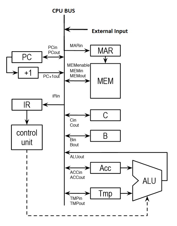
- You have built the 8-bit CPU circuit in the last lab.
- It has TMP, ACC, IR, B and C registers, and the external input EXTin.
It also has the fllowing:- there is a 256 x 8 bit memory attached to the bus through a Memory Address Register(MAR)
- there is a Program Counter (PC) with a built in increment by one function.
- the ALU performs XOR, AND, NOT, and OR operations.
- Machine Instructions for the 8-bit CPU
- Because the memory has 8-bit we can have an 8-bit instruction.
The format of the instruction for the experiment in this lab is:
- The highest two bits indicate the operation. They are called opcode.
- Our 8-bit CPU has the following four operations:
opcode# MNEMONIC DESCRIPTION ============================================================== 00 XOR source, destination XOR the contents of source, destination, and store the result in the destination -------------------------------------------------------------- 01 AND source, destination AND the contents of source, destination, and store the result in the destination -------------------------------------------------------------- 10 NOT source, destination invert the contents of source and store the result in destination -------------------------------------------------------------- 11 OR source, destination OR the contents of source, destination, and store the result in the destination -------------------------------------------------------------- - The source and destination addresses are further divided as follows:
Two bits are assigned for the addressing mode and one bit is specified
for selecting register B or C(B=0, C=1) if the addressing mode is register. - The following table summarizes the addressing modes for this CPU:
        Mode    Mode Description
        ===========================
        00      Register, e.g. B
        ---------------------------
        01      Immediate, e.g. #n
        ---------------------------
        10      indirect, e.g. (B)
        ---------------------------
        11      absolute, e.g. n
        ---------------------------
- The following examples show you the valid assembly language instructions:
1) NOT 2,B ; NOT memory location 2 and store the result in register B. The machine language code for it is as follows: 10110000 00000010 2) XOR #5,(C) ; XOR 5 and the contents of the memory location stored in C and store the result in the memory location stored in C. The machine language code for it is as follows: 00010101 00000101 - Microinstructions for the 8-bit CPU
        Fetch Cycle

        Before an opcode can be interpreted it must be loaded into the IR.
	With our circuit this can be done with the following microcode:


            t1: PCout, MARin. ; set up memory address

            t2: Set MEMio to 0, MEMenable to 1, IRin.;fetch opcode and store in IR

            t3: PC+1out,PCin. ;increment PC
Indirect Cycle Once an opcode is fetched any operands must be fetched. The NOT operation, for example, has two operands: the source and the destination. The type of fetch will depend on the addressing mode used. The following microinstructions can be used to fetch the operand for immediate addressing. t1: PCout, MARin. ;set up to fetch operands address t2: Set MEMenable to 1, MEMio to 0, ACCin. ;move operand to ACC t3: PC+1out, PCin. ;increment PC t4: ALUout. ;get the result onto the bus The first operand is loaded into the accumulator(ACC). The second operand would be loaded into the TEMP register. An example for absolute addressing mode is: t1: PCout, MARin. ;set up to fetch operands address t2: Set MEMenable to 1, MEMio to 0, TMPin. ;move operand address to TMP t3: PC+1out, PCin. ;increment PC t4: TMPout, MARin. ;prepare to get operand t5: Set MEMenable to 1, MEMio to 0, TMPin. ;get operand The indirect cycle for register mode and indirect mode have not been shown but the reader should be able to see how they could be implemented.Execute Cycle Where the results are stored is different for each opcode the CPU can execute. When the destination's "mode" is indirect or absolute (for example, the XOR from above), the results are stored in memory. The following microinstructions are used: t1: ALUout, set MEMenable to 1, MEMio to 1, double click on the MEMclk, to store result in destination. Note that: MAR is assumed to contain the destination address
- Because the memory has 8-bit we can have an 8-bit instruction.
- The difference between absolute and immediate addressing:
- In absolute addressing, the operand is located in
the address specified in the instruction.
For example: NOT 5,B means NOT (or invert) the contents of location 5, and save it in register B. - In immediate addressing, the operand is specified in
the instruction.
For example: AND #5,B means AND the value 5, with value in register B and save the result in B.
EXAMPLE
	Let's execute NOT 2,B ;
	It negates the content in memory location 2 and store the result in register B.
- Translate the assembly code into the machine language code: 10110000 00000010
- LOAD MACHINE CODE TO THE MEMORY: Location Machine code ---------------------------- 00000000 10110000 00000001 00000010 Select 0x00(i.e. b00000000) from ETXin, EXTout, MARin; then close buffer Select 0xB0(i.e. b10110000) from EXTin, EXTout, Set MEMio to 1 to store value to the memory, Set MEMenable to 1 to be able to access the memory, double click on MEMclk; then close the access to the memory Select 0x01(i.e. b00000001) from ETXin, EXTout, MARin; then close buffer Select 0x02(i.e. b00000010) from EXTin, EXTout, Set MEMio to 1 to store value to the memory, Set MEMenable to 1 to be able to access the memory, double click on MEMclk; then close the access to the memory
- Pre-load 8 (00001000) to memory location 2 (0000010) Select 0x02(i.e. b00000010) from ETXin, EXTout, MARin; then close buffer Select 0x08(i.e. b00001000) from EXTin, EXTout, Set MEMio to 1 to store value to the memory, Set MEMenable to 1 to be able to access the memory, double click on MEMclk; then close the access to the memory
- RUN THE PROGRAM: 1. Make PC point to the beginning of your program Select 0x00(i.e. b00000000) from ETXin, EXTout, PCin; then close buffer 2. Fetch the instruction PCout, MARin, MEMenable to 1, MEMio to 0, IRin, MEMenable to 0; 3. Increment PC PC+1out, PCin; then close PC+1out 4. Fetch the address of the operand (absolute mode) PCout, MARin; // close PCout MEMenable to 1, MEMio to 0, TEMin, MEMenable to 0; 5. Fetch the operand TMPout, MARin, MEMenable to 1, MEMio to 0, ACCin, MEMenable to 0; 6. Get the result ALUout, Bin; close ALUout 7. Show result on the bus Bout; showing the result 11110111 on bus
CONCLUSION
With an 8-bit CPU, you can have a RAM attached to it so that you can run some
program in it.  You may have noticed that many devices may be connected
to a common bus by using tri-state buffers.
5. Lab Assignments
 Copyright: Department of Computer Science, University of Regina.
- In absolute addressing, the operand is located in
the address specified in the instruction.