Review Logisim - Design a shift register
Objectives
- Review Logisim in the CS201 lab material and particularly Introduction to Logisim
- Review D-flip-flop and Multiplexers (MUX-4)
- Build a 4-bit shift register circuit
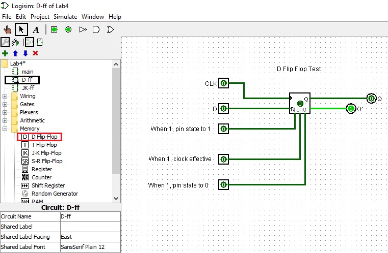
Review D-Flip-Flop
The D flip-flop(shown below) lets the input at D propogate through to Q on the positive going edge of the clock. The present state-next state chart illustrates the behavior of the D flip-flop. Basically Q(t+1) = D, which is the characteristic equation.
	Characteristic Table		Excitation Table
	====================            ===================
	D  Q(t+1)  Operation            Q(t)  Q(t+1)   D
	====================		===================
	0    0     Reset                 0      0      0
	--------------------            -------------------
	1    1     Set                   0      1      1
	====================            -------------------
					 1      0      0
					-------------------
					 1      1      1
					===================
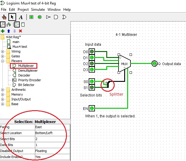
Review Multiplexers (MUX-4)
A multiplexer is a combinational logic circuit designed to select one of several input lines to a single common output line accordig to the selection control signals. For example, 2-1 Multiplexer has one control signal, 4-1 Mutiplexer has two control signals, 8-1 Multipleaxer has three control signals and so on.Here is a demonstration of 4-1 Multilexer with four input lines D0, D1, D2, D3 for your reference.
	Truth Table of a 4-1 Multiplexer (MUX 4)
	========================================
	Input	Selection Output
	----------------------------------------
	  	S1  S0      Q
	D0	0   0       D0
	D1	0   1       D1
	D2	1   0       D2
	D3	1   1       D3
	-----------------------------------------
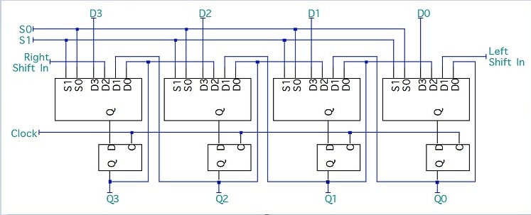
Build a 4-bit Shift Register
We can build a 4-bit shift register circuit using four D-flip-flops and four multiplexers (MUX-4).We can have selection inputs control over it.
        Select Inputs   Function
        S1      S0
        ------------------------
        0       0       Store
        0       1       Shift left
        1       0       shift right
        1       1       Load
Here is the design diagram: