ARM Subroutine/procedure/function Calls
Objectives
        Explore ARM subroutine calls and implement them in Keil uVision5.
        - Using   BL SUB_Name,  and MOV PC, LR  or BX  LR
        - Study and using stack
You have learned user defined functions in CS110 and procedure calls
in MIPS. In this lab, we need to deal with function/procedure call/return
in the ARM assembly lauguage environment.
ARM processors do not provide a fully automatic subroutine call/return mechanism like other processors. ARM's branch and link instruction, BL, automatically saves the return address in the register R14 (i.e. LR). We can use MOV PC, LR at the end of the subroutine to return back to the instruction after the subroutine call BL SUBROUTINE_NAME. A SUBROUTINE_NAME is a label in the ARM program.
ARM Unconditional and Conditional Subroutine Calls
  Mnemonic		Meaning
==============================================================================
  BL  SUB_A   		; Branch to SUB_A with link save return address in R14
------------------------------------------------------------------------------
  CMP    R1, R2		; branch conditionally
  BLLT   SUB_B		; if R1 < R2, then branch to SUB_B
  BLLE   SUB_C		; if R1 <= R3, then branch to SUB_C
  BLGT   SUB_D		; if R1 > R2, then branch to SUB_D
  BLGE   SUB_F		; if R1 >= R2, then branch to SUB_F
------------------------------------------------------------------------------
  MOV    PC, LR 	; get the control of execution back after executing
			; a subroutine/procedure
------------------------------------------------------------------------------
  BX  LR		; Return to the calling function
------------------------------------------------------------------------------
  Using PROC and ENDP as a pair for procedures
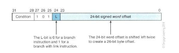
Here is the encoding format of ARM's branch and branch-with-link instructions for your reference.
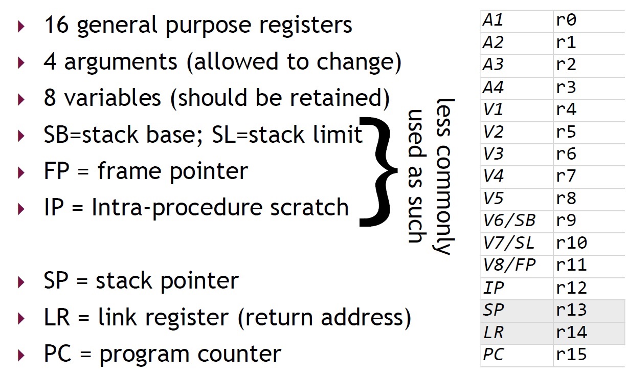
Register Use in the ARM Procudure Call Standard
An Example Using a Subroutine Call
;The semicolon is used to lead an inline documentation
;When you write your program, you could have your info at the top document lock
;For Example:
;;;;Your Name:
;;;;Student Number:
;;;;Lab#:
;;;;

;;; Directives
          PRESERVE8
          THUMB
;;; Equates
	;; Empty
;;; Includes
	;; Empty

;;; Vector Definitions
; Vector Table Mapped to Address 0 at Reset
; Linker requires __Vectors to be exported

          AREA    RESET, DATA, READONLY
          EXPORT  __Vectors

__Vectors
          DCD  0x20001000     ; stack pointer value when stack is empty
          DCD  Reset_Handler  ; reset vector

          ALIGN

;Your Data section
;AREA DATA

SUMP      DCD SUM
SUMP2     DCD SUM2
N         DCD 5

	AREA    MYRAM, DATA, READWRITE
SUM 	DCD 0
SUM2 	DCD 0


;; The program Linker requires Reset_Handler

          AREA    MYCODE, CODE, READONLY

   	  ENTRY
   	  EXPORT Reset_Handler

;;;;;Procedure definitions;;;;

SUMUP 	PROC
	ADD 	R0, R0, R1 	;Add number into R0
	SUBS 	R1, R1, #1 	;Decrement loop counter R1
	BGT 	SUMUP 		;Branch back if not done
	;MOV 	PC, LR
	BX 	LR
	ENDP

;;;users main program;;;;;

Reset_Handler


	LDR 	R1, N 		;Load count into R1

	MOV 	R0, #0 		;Clear accumulator R0

	BL  	SUMUP

	LDR 	R3, SUMP	;Load address of SUM to R3
	STR 	R0, [R3]	;Store SUM

	LDR     R4, [R3]

	MOV     R7, #8

	LDR 	R5, SUMP2	;Load address of SUM2 to R5
	STR 	R7, [R5]	;Store SUM2

	LDR     R6, [R5]


STOP
        B STOP

	END
Introduction to Stack
	The stack is a data structure, known as last in first out (LIFO).
	In a stack, items entered at one end and leave in the reversed order.
	Stacks in microprocessors are implemented by using a stack pointer
	to point to the top of the stack in memory.
	As items are added to the stack (pushed), the stack pointer is
	moving up, and as items are removed from the stack (pulled or popped),
	the stack pointer is moved down.
Here is a picture to show the idea of Stack LIFO structure.
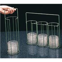
The picture is adopted from this page.
Stack Types
ARM stacks are very flexible since the implementation is completely left to the software. Stack pointer is a register that points to the top of the stack. In the ARM processor, any one of the general purpose registers could be used as a stack pointer. Since it is left to the software to implement a stack, different implemenation choices result different types of stacks. Normally, there are two types of the stacks depending on which way the stack grows.
1.	Ascending Stack - When items are pushed on to the stack,
	the stack pointer is increasing.  That means the stack grows
	towards higher address.

2.	Descending Stack - When items are pushed on to the stack,
	the stack pointer is decreasing.  That means the stack is growing
	towards lower address.
Depending on what the stack pointer points to we can categorize the stacks into the following two types:
1.	Empty Stack - Stack pointer points to the location in which the next/first item
	will be stored.
	e.g. A push will store the value, and increment the stack pointer
	for an  Ascending Stack.

2. 	Full Stack - Stack pointer points to the location in which the last item
	was stored.
	e.g. A pop will decrement the stack pointer and pull the value
	for an Ascending Stack.
So now we can have four possible types of stacks. They are
- full-ascending stack,
- full-descending stack,
- empty-ascending stack,
- empty-descending stack.
Here are some instructions used to deal with stack:
Push registers onto and pop registers off a full-descending stack.
	Examples:
	PUSH {R0, R4-R7}	;Push R0, R4, R5, R6, R7 onto the stack
	PUSH {R2, LR}		;Push R2 and the link register onto the stack
	POP  {R0, R6, LR}	;Pop R0, R6, and LR from the stack
	POP  {R0, R5, PC}	;Pop R0, R5, and PC from the stack
				;then branch to the new PC
=============================================================================
	Reference:  Cortex-M3 Devices Generic User Guide.  Page 3-29 to 3-30.
Subroutine and Stack
	A subroutine call can be implemented by pushing the return
	address on the stack and then jumping to the branch target
	address.  When the subroutine is done, remember to pop out
	the saved information so that it will be able to return to
	the next instruction immediately after the calling point.
An Example of Using Stack
;; Put your name and a title for the program here
;;

;;; Directives
            PRESERVE8
            THUMB


;;; Equates
;;; The EQU directive gives a symbolic name to a numeric constant,
;;; a register-relative value or a PC-relative value.
;;; Use EQU to define constants.

INITIAL_MSP	EQU	0x20001000	; Initial Main Stack Pointer Value
			; Allocating 1000 bytes to the stack as it grows down.
			; RAM starts at address 0x20000000


; Vector Table Mapped to Address 0 at Reset
; Linker requires __Vectors to be exported

            AREA    RESET, DATA, READONLY
            EXPORT  __Vectors

__Vectors	DCD	INITIAL_MSP	; stack pointer value when stack is empty
        	DCD	Reset_Handler	; reset vector
		ALIGN

; The program
; Linker requires Reset_Handler

            AREA    MYCODE, CODE, READONLY

		    ENTRY
		    EXPORT	Reset_Handler

		    ALIGN
;;; Define Procedures

function1	PROC	     ;Using PROC and ENDP for procedures
	PUSH 	{R5,LR}      ;Save values in the stack

	MOV	R5,#8        ;Set initial value for the delay loop

delay
	SUBS	R5, R5, #1
	BNE	delay

	POP	{R5,PC}	;pop out the saved value from the stack,
			;check the value in the R5 and if it is the saved value


	ENDP

;;;;;;;user main program;;;;;;;;

Reset_Handler


     	MOV 	R0, #0x75
        MOV 	R3, #5
	PUSH	{R0, R3} 	 ;Notice the stack address is 0x200000FF8
        MOV 	R0, #6
        MOV 	R3, #7
	POP	{R0, R3}	 ;Should be able to see R0 = #0x75 and R3 = #5 after pop


Loop

	ADD	R0, R0, #1
	CMP	R0, #0x80
	BNE	Loop


	MOV 	R5, #9	;; prepare for function call


    	BL 	function1

	MOV 	R3, #12

stop
        B 	stop


        END
Lab Assignment
![]() Copyright: Department of Computer Science, University of Regina.
Copyright: Department of Computer Science, University of Regina.