ARM Data-processing Instructions
Objectives
1.       To investigate Arithmetic Operations and more other instructions.

2.	 To implement them in Keil uVision5.
ARM Registers and the Conventions of Use
As mentioned in the previous lab, ARM has 16 programmer-visiable registers
and a Current Program Status Register, CPSR.
Here is a picture to show the ARM register set.
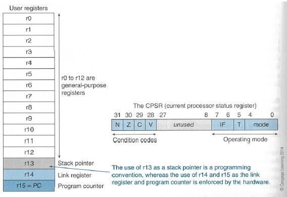
	R0 to R12 are the general-purpose registers.
	R13 is reserved for the programmer to use it as the stack pointer.
	R14 is the link register which stores a subroutine return address.
	R15 contains the program counter and is accessible by the programmer.

	CPSR: current program status register (32 bit)
	Stores the status of the previous ALU operation.
	4 flags
	N = 1, if result was negative
	Z = 1, if result was zero
	C = 1, if result had a carry-out
	V = 1, if result was an overflow
	These can be used to make decisions later on.
Each ARM instruction is encoded into a 32-bit word. Access to memory is provided only by Load and Store instructions.
ARM data-processing instructions operate on data and produce new value.
They are not like the branch instructions that control the operation of the processor and sequencing of instructions.
ARM instructions have the following general format:
Label Op-code operand1, operand2, operand3 ; comment
Arithmetic Instructions
Arithmetic instructions are very basic and frequently used in your
ARM programming.
Here is a table that demonstrates the usage of the ARM
processor's arithmetic instructions with examples.
  Instruction		Mnemonic		Meaning
========================================================================
  Addition		ADD   R0, R1, R2	; R0 = R1 + R2
------------------------------------------------------------------------
  Addition		ADDS  R0, R1, R2	; R0 = R1 + R2,
						; and FLAGs are updated
------------------------------------------------------------------------
  Subtraction		SUB   R1, R2, R3 	; R1 = R2 - R3
------------------------------------------------------------------------
  Subtraction		SUBS  R1, R2, R3	; R1 = R2 - R3,
						; and FLAGs are updated
------------------------------------------------------------------------
			SUBS  R7, R6, #20       ; R7 = R6 - 20
						; Sets the flags on the result
------------------------------------------------------------------------
  Reverse Subtraction	RSB R4, R4, #120        ; R4 = 120 - R4
------------------------------------------------------------------------
  Multiply		MUL   R0, R1, R2        ; R0 = R1 * R2
------------------------------------------------------------------------

  Division		SDIV  R0, R2, R4        ; Signed divide, R0 = R2/R4
------------------------------------------------------------------------
			UDIV  R8, R8, R1 	; Unsigned divide, R8 = R8/R1.
------------------------------------------------------------------------
Examples of Move Instructions
	Mnemonic	    Meaning
------------------------------------------------------------------------
	MOV   R1, #0xFA05 ; Write value of 0xFA05 to R1, flags are not updated
------------------------------------------------------------------------
	MOVS R11, #0x000B ; Write value of 0x000B to R11, flags get updated
------------------------------------------------------------------------
	MOVS R10, R12     ; Write value in R12 to R10, flags get updated
------------------------------------------------------------------------
	MOV R3, #23       ; Write value of 23 to R3
------------------------------------------------------------------------
	MOV R8, SP        ; Write value of stack pointer to R8
------------------------------------------------------------------------
	MVNS R2, #0xF     ; Write value of 0xFFFFFFF0 (bitwise inverse of 0xF)
                          ; to the R2 and update flags.
------------------------------------------------------------------------
Logical Operation Instructions
------------------------------------------------------------------------
	AND R9, R2, R1			; R9 = R2 AND R1
------------------------------------------------------------------------
	AND R9, R2, #0xFF00		; R9 = R2 AND #0xFF00
------------------------------------------------------------------------
	ANDS R9, R8, #0x19            ; flags get updated
------------------------------------------------------------------------
	ORR R9, R2, R1			; R9 = R2 OR R1
------------------------------------------------------------------------
	ORR R9, R2, #0xFF00
------------------------------------------------------------------------
	EOR  R7, R11, R10		; R7 = R11 XOR R10
------------------------------------------------------------------------
	EORS R7, R11, #0x18181818     ; flags get updated
------------------------------------------------------------------------
	BIC R0, R1, #0xab		; R0 = R1 AND (NOT(#0xab))
------------------------------------------------------------------------
Conditional Execution of Instructions
Each ARM instruction is encoded into a 32-bit word.
The basic encoding format for the instructions such as
Load, Store, Move, Arithmetic, and Logic instructions, is as follows:
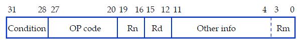
An instruction specifies a conditional execution code
(Condition), the OP code, two or three registers (Rn, Rd,
and Rm), and some other information.
Here is a more detailed description.
All the ARM instructions are conditionally executed depending on a condition specified in the instruction(bits 31-28).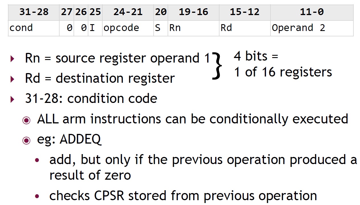
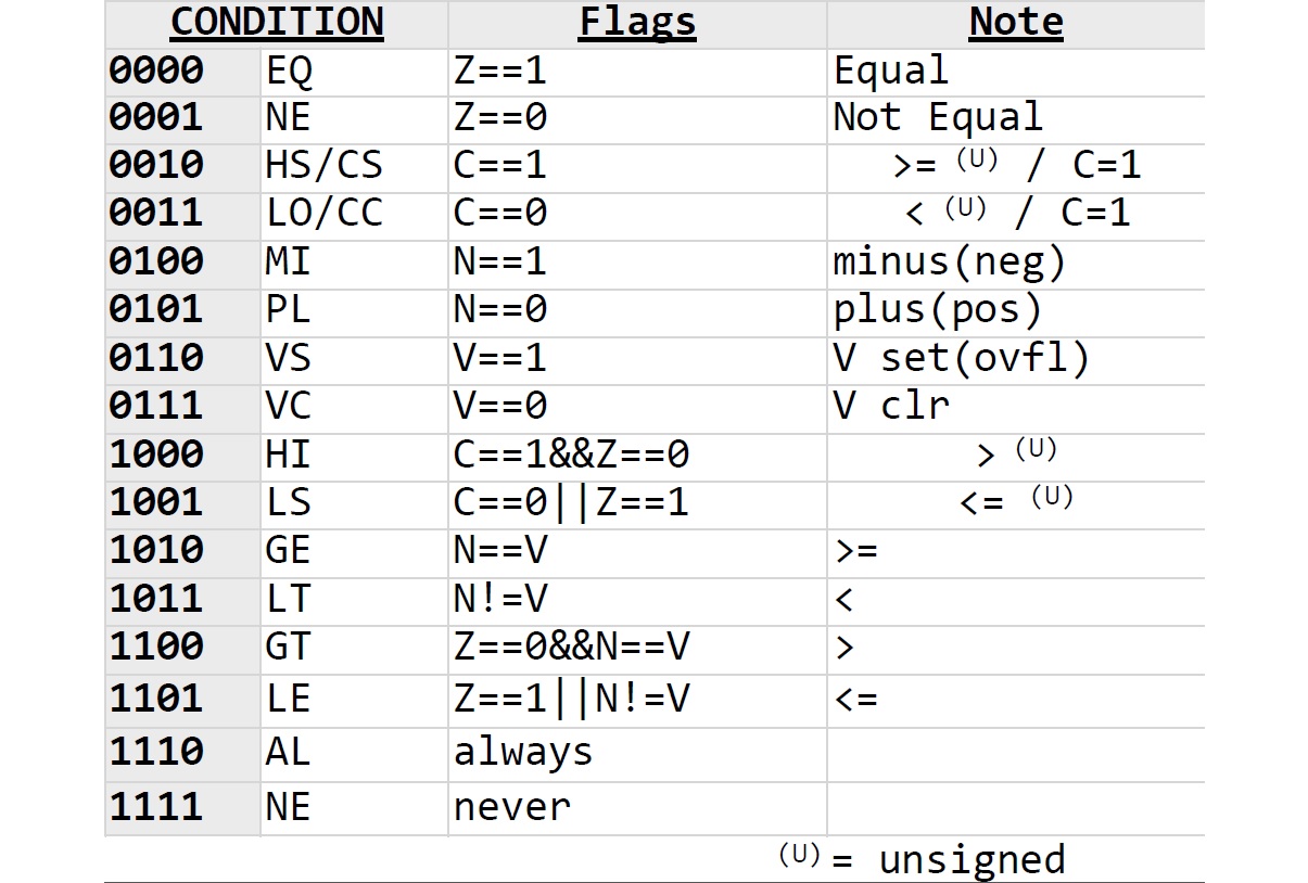
- The instruction is executed only if the current state of the
processor condition code flag satisfies the condition
specified in bits b31-b28 of the instruction.
For example:
		CMP R0, #25		; flags are updated according to (R0 - #25)
		ADDGT R1, R2, #12
- The instructions whose condition does not meet the processor condition code flag are not executed.
- One of the conditions is used to indicate that the instruction is always executed.
Examples of Shift Instructions
------------------------------------------------------------------------
	LSL R4, R5, #2  ; Logical shift left by 2 bits
------------------------------------------------------------------------
	LSR R4, R5, #6  ; Logical shift right by 6 bits
------------------------------------------------------------------------
	LSLS R1, R2, #3 ; Logical shift left by 3 bits with flag update
------------------------------------------------------------------------
	ROR R4, R5, R6  ; Rotate right by the value in the bottom byte of R6
------------------------------------------------------------------------
	RRX R4, R5      ; Rotate right with extend (one bit only).
------------------------------------------------------------------------
Here is a link for your references:
Cortex-M3 Devices Generic User Guide. Section 3.5 and 3.6.
An Example of Using Arithmetic Instructions
;The semicolon is used to lead an inline documentation
;
;When you write your program, you could have your info at the top document block
;For Example:  Your Name, Student Number, what the program is for, and what it does etc.
;
;	This program will catculate the value of the following function:
;	f(x) = 5x^2 - 6x + 8  when x = 7.
;

;;; Directives
          PRESERVE8
          THUMB

; Vector Table Mapped to Address 0 at Reset
; Linker requires __Vectors to be exported

          AREA    RESET, DATA, READONLY
          EXPORT  __Vectors

__Vectors
	  DCD  0x20001000     ; stack pointer value when stack is empty
          DCD  Reset_Handler  ; reset vector

          ALIGN

; The program
; Linker requires Reset_Handler

		AREA    MYCODE, CODE, READONLY

		ENTRY
		EXPORT Reset_Handler


Reset_Handler

;;;;;;;;;;User Code Start from the next line;;;;;;;;;;;;

		MOV R0, #7	; x = 7

		MUL R1, R0, R0	; R1 = x^2
		MOV R4, #5
		MUL R1, R1, R4

		MOV R5, #6
		MUL R2, R0, R5	; R2 = 6x

		SUB R3, R1, R2	; R3 = 5x^2 - 6x
		ADD R3, R3, #8	; R3 = 5x^2 - 6x + 8

		ALIGN
STOP
   	  	B  STOP

		END		; End of the program
Load and Store Instructions
To access memory, we can only use Load and Store instructions.
	LDR dest, expression
	LDR R6, [R4]	; load R6 with the value in the memory whose address is in R4

	STR STR{cond} srce,[base],offset

	STR R0,[R1]		; store R0 in the byte address R1
	STR R0,[R1,#20]		; store R0 in the byte address R1+20
	STR R0,[R1,R2,LSL#2]	; store R0 in the address given by R1+R2*4

	Examples:
	LDR 	R0, NUM			; load R0 with the value of NUM in memory
	LDR	R6, = NUM		; Load the address of NUM to R6
	MOV	R0, #0x001C		; Load the value to the R0
	STR	R0, [R6]		; Store the value in R0 to NUM
Another Example
;The semicolon is used to lead an inline documentation
;When you write your program, you could have your info at the top document block
;For Example:  Your Name, Student Number, what the program is for, and what it does etc.
;
;       See if you can figure out what this program does
;

;;; Directives
          PRESERVE8
          THUMB

; Vector Table Mapped to Address 0 at Reset
; Linker requires __Vectors to be exported

          AREA    RESET, DATA, READONLY
          EXPORT  __Vectors

__Vectors
	  DCD  0x20001000     ; stack pointer value when stack is empty
          DCD  Reset_Handler  ; reset vector

          ALIGN

;Your Data section
;AREA DATA

SUMP    DCD SUM
NUM1 	DCD 5
NUM2 	DCD 7
; The DCD directive allocates one or more words of memory,
; aligned on four-byte boundaries,
; and defines the initial runtime contents of the memory.
;
; For example,   data1   DCD     1,5,20
; Defines 3 words containing decimal values 1, 5, and 20

 	 AREA    MYRAM, DATA, READWRITE
SUM 	DCD 0


; The program
; Linker requires Reset_Handler

          AREA    MYCODE, CODE, READONLY

   	  ENTRY
   	  EXPORT Reset_Handler


Reset_Handler
;;;;;;;;;;User Code Start from the next line;;;;;;;;;;;;

   	LDR R1, NUM1
    	LDR R2, NUM2


	MOV R0, #0

	ADD R0, R1, R2

	SUBS R0, R0, #1

	LSLS R3, R0, #2 	; Logical shift left by 2 bits with flag update

	LDR R4, SUMP
	STR R3, [R4]

	LDR R6, [R4]

 	ALIGN
STOP
        B  STOP


	END
Lab Assignment
![]() Copyright: Department of Computer Science, University of Regina.
Copyright: Department of Computer Science, University of Regina.