ARM Addressing Modes
Objectives
        Explore ARM addressing modes
	- Register Addressing Mode
	- Register Indirect Addressing Mode
	- ARM's Autoindexing Pre-indexed Addressing Mode
	- ARM's Autoindexing Post-indexing Addressing Mode
	- Program Counter Relative (PC Relative) Addressing Mode
	- and so on
Review of ARM Registers Set
As mentioned in the previous lab, ARM has 16 programmer-visiable registers
and a Current Program Status Register, CPSR.
Here is a picture to show the ARM register set.
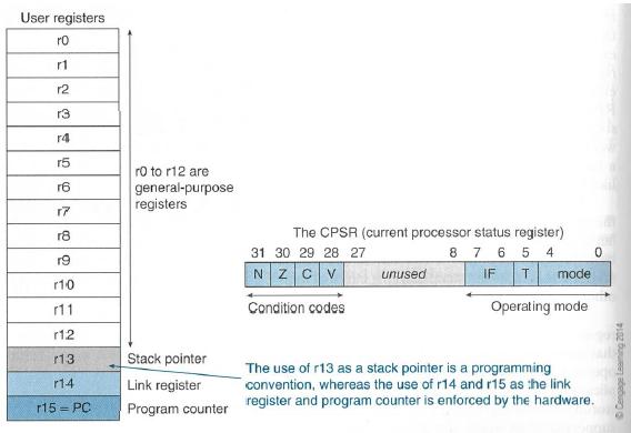
	R0 to R12 are the general-purpose registers.
	R13 is reserved for the programmer to use it as the stack pointer.
	R14 is the link register which stores a subroutine return address.
	R15 contains the program counter and is accessible by the programmer.

	Conditonion code flags in CPSR:
	N - Negative or less than flag
	Z - Zero flag
	C - Carry or bowrrow or extendedflag
	V - Overflow flag
	The least-significant 8-bit of the CPSR are the control bits of the system.
	The other bits are reserved.
Summary of ARM addressing Modes
There are different ways to specify the address of the operands for any given operations such as load, add or branch. The different ways of determining the address of the operands are called addressing modes. In this lab, we are going to explore different addressing modes of ARM processor and learn how all instructions can fit into a single word (32 bits).
Name			Alternative Name	ARM Examples
------------------------------------------------------------------------
Register to register    Register direct		MOV R0, R1
------------------------------------------------------------------------
Absolute		Direct			LDR R0, MEM
------------------------------------------------------------------------
Literal			Immediate		MOV R0, #15
						ADD R1, R2, #12
------------------------------------------------------------------------
Indexed, base		Register indirect 	LDR R0, [R1]
------------------------------------------------------------------------
Pre-indexed,		Register indirect  	LDR R0, [R1, #4]
base with displacement  with offset
------------------------------------------------------------------------
Pre-indexed,		Register indirect	LDR R0, [R1, #4]!
autoindexing		pre-incrementing
------------------------------------------------------------------------
Post-indexing,		Register indirect	LDR R0, [R1], #4
autoindexed		post-increment
------------------------------------------------------------------------
Double Reg indirect	Register indirect	LDR R0, [R1, R2]
			Register indexed
------------------------------------------------------------------------
Double Reg indirect	Register indirect	LDR R0, [R1, R2, LSL #2]
with scaling		indexed with scaling
------------------------------------------------------------------------
Program counter relative			LDR R0, [PC, #offset]
------------------------------------------------------------------------
Literal Addressing Mode
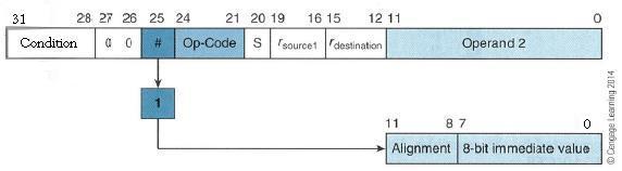
	Examples	    	  Meaning
------------------------------------------------------------------------
	CMP R0, #22
------------------------------------------------------------------------
	ADD R1, R2, #18
------------------------------------------------------------------------
	MOV R1, #30
------------------------------------------------------------------------
	MOV R1, #0xFF
------------------------------------------------------------------------
	CMN R0, #64	; R0 + #64, update the N, Z, C and V flags
------------------------------------------------------------------------
	CMPGT SP, R7, LSL #2	; update the N, Z, C and V flags
------------------------------------------------------------------------
Register Indirect Addressing Mode
Register indirect addressing means that the location of an operand is held in a register. It is also called indexed addressing or base addressing.
Register indirect addressing mode requires three read operations to access an operand. It is very important because the content of the register containing the pointer to the operand can be modified at runtime. Therefore, the address is a variable that allows the access to the data structure like arrays.
- Read the instruction to find the pointer register
- Read the pointer register to find the oprand address
- Read memory at the operand address to find the operand
	LDR	R2, [R0]	; Load R2 with the word pointed by R0
-------------------------------------------------------------------------------------
	STR	R2, [R3]	; Store the word in R2 in the location pointed by R3
Register Indirect Addressing with an Offset
ARM supports a memory-addressing mode where the effective address of an operand is computed by adding the content of a register and a literal offset coded into load/store instruction. For example,
	Instruction		Effective Address
-------------------------------------------------------------------------------------
	LDR R0, [R1, #20]	R1 + 20    ; loads R0 with the word pointed at by R1+20
-------------------------------------------------------------------------------------
ARM's Autoindexing Pre-indexed Addressing Mode
This is used to facilitate the reading of sequential data in structures such as arrays, tables, and vectors. A pointer register is used to hold the base address. An offset can be added to achieve the effective address. For example,
	Instruction		Effective Address
-------------------------------------------------------------------------------------
	LDR R0, [R1, #4]!       R1 + 4     ; loads R0 with the word pointed at by R1+4
					   ; then update the pointer by adding 4 to R1
-------------------------------------------------------------------------------------
ARM's Autoindexing Post-indexing Addressing Mode
This is similar to the above, but it first accesses the operand at the location pointed by the base register, then increments the base register. For example,
	Instruction		Effective Address
-------------------------------------------------------------------------------------
	LDR R0, [R1], #4        R1         ; loads R0 with the word pointed at by R1
					   ; then update the pointer by adding 4 to R1
-------------------------------------------------------------------------------------
Program Counter Relative (PC Relative) Addressing Mode
Register R15 is the program counter. If you use R15 as a pointer register to access operand, the resulting addressing mode is called PC relative addressing. The operand is specified with respect to the current code location. Please look at this example,
	Instruction		Effective Address
-------------------------------------------------------------------------------------
	LDR R0, [R15, #24]      R15 + 24  ; loads R0 with the word pointed at by R15+24
-------------------------------------------------------------------------------------
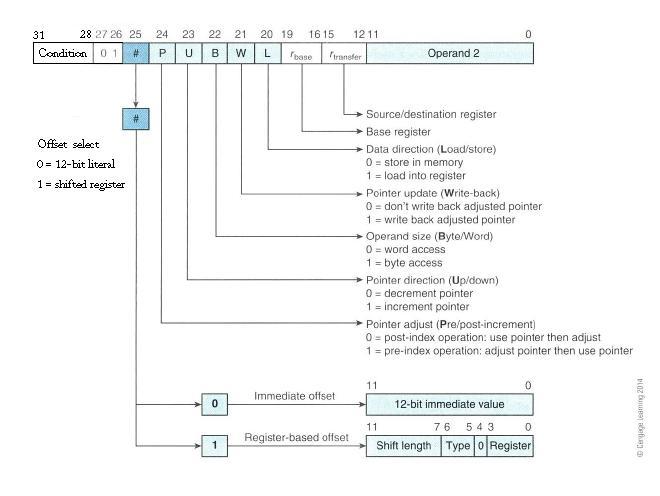
ARM's Load and Store Encoding Format
The following picture illustrates the encoding format of the ARM's load and store instructions, which is included in the lab material for your reference. Memory access operations have a conditional execution field in bit 31, 03, 29, and 28. The load and store instructions can be conditionally executed depending on a condition specified in the instruction. Now look at the following examples:
	CMP	R1, R2
---------------------------------------------------------------
	LDREQ   R3, [R4]
---------------------------------------------------------------
  	LDRNE	R3, [R5]
Encoding Format of ARM's load and store instructions
Summary of ARM's Indexed Addressing Modes
Addressing Mode		Assembly Mnemonic	Effective address   Final Value in R1
------------------------------------------------------------------------------------
Pre-indexed, base	LDR  R0, [R1, #d]	R1 + d		    R1
    unchanged
------------------------------------------------------------------------------------
Pre-indexed, base	LDR  R0, [R1, #d]!	R1 + d		    R1 + d
    updated
------------------------------------------------------------------------------------
Post-indexed, base      LDR  R0, [R1], #d	R1		    R1 + d
    updated
------------------------------------------------------------------------------------
An Example Program of Using Post-indexing Mode
;The semicolon is used to lead an inline documentation
;When you write your program, you could have your info at the top document block
;For Example:  Your Name, Student Number, what the program is for, and what it does etc.

;	  This program will find the sum of an array.


;;; Directives
          PRESERVE8
          THUMB

; Vector Table Mapped to Address 0 at Reset
; Linker requires __Vectors to be exported

          AREA    RESET, DATA, READONLY
          EXPORT  __Vectors

__Vectors
	  DCD  0x20001000     ; stack pointer value when stack is empty
          DCD  Reset_Handler  ; reset vector

          ALIGN

;Your Data section
	;AREA DATA
SUMP    DCD SUM

N 	DCD 5
NUM1 	DCD 3, -7, 2, -2, 10
POINTER DCD NUM1

	AREA    MYRAM, DATA, READWRITE
SUM 	DCD 0

; The program
; Linker requires Reset_Handler

          AREA    MYCODE, CODE, READONLY

   	  ENTRY
   	  EXPORT Reset_Handler


Reset_Handler

;;;;;;;;;;User Code Start from the next line;;;;;;;;;;;;

	LDR R1, N	; load size of array -
			; a counter for how many elements are left to process

	LDR R2, POINTER		; load base pointer of array

	MOV R0, #0		; initialize accumulator

LOOP
	LDR R3, [R2], #4	; load value from array,
				; increment array pointer to next word
	ADD R0, R0, R3		; add value from array to accumulator
	SUBS R1, R1, #1		; decrement work counter
	BGT LOOP		; keep looping until counter is zero
	LDR R4, SUMP		; get memory address to store sum
	STR R0, [R4]		; store answer

	LDR R6, [R4]		; Check the value in the SUM

STOP
	B  STOP

	END
Another Example
;The semicolon is used to lead an inline documentation
;
;When you write your program, you could have your info at the top document block
;For Example: Your Name, Student Number, what the program is for, and what it does etc.
;
;	This program will count the length of a string.
;

;;; Directives
          PRESERVE8
          THUMB

; Vector Table Mapped to Address 0 at Reset
; Linker requires __Vectors to be exported

          AREA    RESET, DATA, READONLY
          EXPORT  __Vectors

__Vectors
	  DCD  0x20001000     ; stack pointer value when stack is empty
          DCD  Reset_Handler  ; reset vector

          ALIGN

;;;;;;;;;;;;;;;;;;;;;;;;;;;;;;;;;;;;;;;;;;;;;;;;;;;;;;;;;;;;;;;;;;;;;;;;;;;;;;;;;
; Character array - string
; This type of format will construct a C string and null terminate.
; This means you can tell when the string ends
;;;;;;;;;;;;;;;;;;;;;;;;;;;;;;;;;;;;;;;;;;;;;;;;;;;;;;;;;;;;;;;;;;;;;;;;;;;;;;;;

string1
	DCB	"Hello world!",0

; The program
; Linker requires Reset_Handler

	AREA    MYCODE, CODE, READONLY

	ENTRY
	EXPORT Reset_Handler


Reset_Handler

;;;;;;;;;;User Code Start from the next line;;;;;;;;;;;;


	LDR  	R0, = string1   ; Load the address of string1 into the register R0

	MOV	R1, #0  	; Initialize the counter counting the length of string1

loopCount

	LDRB	R2, [R0], #1	; Load the character from the address R0 contains
				; and update the pointer R0
				; using Post-indexed addressing mode

	CBZ	R2, countDone   ; If it is zero...remember null terminated...
				; You are done with the string. The length is in R1.

	;ADD	R0, #1;         ; Otherwise, increment index to the next character

	ADD	R1, #1;         ; increment the counter for length

	B	loopCount


countDone

	B	countDone

	END			; End of the program
Lab Assignment
![]() Copyright: Department of Computer Science, University of Regina.
Copyright: Department of Computer Science, University of Regina.