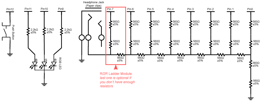
The circuit this week combines an RGB LED and a digital to analog conversion circuit called an R/2R ladder.
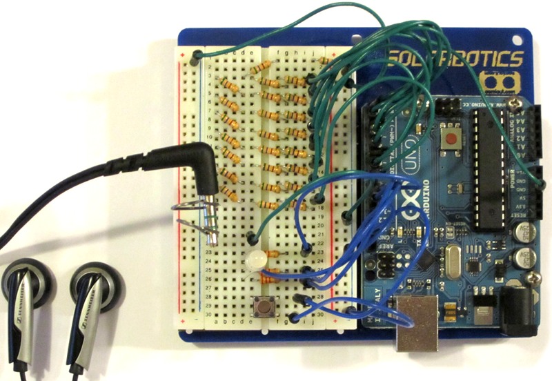
Build the following circuit. Connect your headphones by using the two paperclips to clamp the tip and base of the headphone jack. If you have enough 560Ω resistors, you should build all eight R/2R modules. If you don't have enough, you should ask around or remove one module. If you leave out modules, you will have to halve sound levels for each missing module.
Use this code to test your circuit. You will know everything is working if pushing the button causes the RGB LED to alternate between red, green and blue and if you can hear a tone fading from loud to quiet in your headphones.
/* Lab 9 First Build Sketch
  * Written Nov 15 2011 by Alex Clarke
  */
 // Pin Constants
 const int redPin = 9;
 const int greenPin = 10;
 const int bluePin = 11;
 const int buttonPin = 12;

 // Color Variables
 int color = 0;
 // Button State Variables
 float curButton = HIGH;
 float lastButton = HIGH;

 // variables for tone
 int value;
 int toneOn;
 int increment = 1;

 void setup()
 {
   // Set up RGB LED pins
   pinMode(redPin, OUTPUT);
   pinMode(greenPin, OUTPUT);
   pinMode(bluePin, OUTPUT);

   //Set up button pin
   pinMode(buttonPin, INPUT);
   // Trick to make this a pull up button
   // Other side of button must be attached to ground
   digitalWrite(buttonPin, HIGH);
   // Quick way to set pins 0 to 7 to OUTPUT
   DDRD = B11111111;
 }

 void loop()
 {
   //Store Last Button State
   lastButton = curButton;

   //Read Current Button
   curButton = digitalRead(buttonPin);


   //If button was just pressed cycle color
   if (curButton == LOW && lastButton == HIGH)
   {
     color++;
   }
   //Set RGB LED to a color
   if (color == 0) //RED
   {
     digitalWrite(redPin, HIGH);
     digitalWrite(greenPin, LOW);
     digitalWrite(bluePin, LOW);
   }
   else if (color == 1) //GREEN
   {
     digitalWrite(redPin, LOW);
     digitalWrite(greenPin, HIGH);
     digitalWrite(bluePin, LOW);
   }
   else if (color == 2) //BLUE
   {
     digitalWrite(redPin, LOW);
     digitalWrite(greenPin, LOW);
     digitalWrite(bluePin, HIGH);
   }
   else //Invalid color, reset to RED
   {
     color = 0;
   }


   if (toneOn == true)
   {
     PORTD = value; //divide this by 2 for each missing R/2R module
   }
   else
   {
     PORTD = 0;
   }

   toneOn = !toneOn;
   value+= increment;

   if (value == 255 || value == 0)
   {
     increment = -increment;
   }
   delayMicroseconds(1000000l/440);
 }
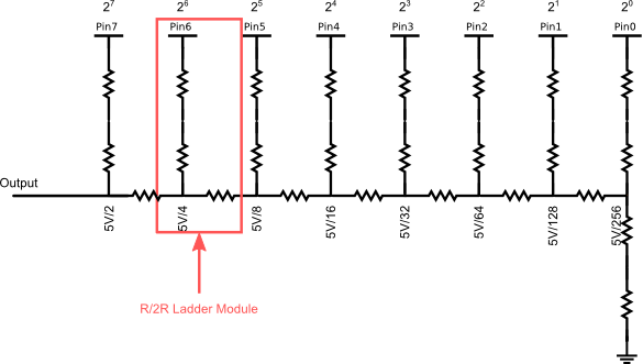
If you want to be able to turn a digital signal into an analog signal you need to use some kind of Digital to Analog Converter or DAC. The R/2R ladder circuit in this lab is a classic example of a DAC. Because of the ladder arrangement of the resistors in this circuit, a current division effect is created that makes it so that the signal nearest to the output is delivered at half voltage. The next nearest at half that voltage, and so on through each ladder module. In this way each signal pin contributes a voltage that is appropriate to the binary value in the digital signal.
Just as the values of each binary digit can be added together to
tell us the value of the a binary number, this circuit adds together
the voltages indicated to create an analog representation of the binary
input.The output of this circuit will not quite reach the reference voltage of 5V. Instead it will have an error of reference/2 N
where N is the number of modules in the ladder. In our circuit that
means that the error will be 5V/256 or 0.1953V. This also happens to be
the voltage step size – the voltage that represents a difference
of 1 in the digital signal. As you add more modules at the output end,
the voltage step size will shrink and you can more accurately reach
specific voltage levels.
Our implementation is good enough for experimenting with, but the headphones can introduce noise into the resistor network and distort the audio signal. Normally a the output of the resistor ladder is used to drive a special circuit called an op-amp. The op-amp copies the exact voltages from the ladder circuit to a isolated power supply. You can learn more about R/2R circuits on the IKALogic website.
When you learned to wire up buttons, you learned to use an external pull resistor. Some buttons are pull up, some are pull down. Many microcontrollers have a pull resistor built in to their input pins that you can use to simplify your circuit designs. The Arduino has built-in pull up resistors. Other microcontrollers have built-in pull down.
For example, in this lab there's a button on pin 12 with no pull resistor. Yet it works. Pin 12 has been put into built-in pullup mode. There are two ways to do this. The first is what we do in the First Build code:
  //Set a pin to input pull up mode (old way).
  pinMode(buttonPin, INPUT); // Put pin in input mode
  digitalWrite(buttonPin, HIGH); // Writing HIGH to an input activates its pull up resistor
The second combines both into one step:
  //Set a pin to input pull up mode (new way).
  pinMode(buttonPin, INPUT_PULLUP);
Your Arduino has three built-in port registers. These are a bit like shift registers - you can write a single value to them and it will be presented all at once. You can't chain them together though. You can learn about all of them on the Arduino.cc Port Manipulation page.
Pins 0 to 7 are all part of port D. You can initialize each of these pins to input or output mode with a single assignment to DDRD – the Port D Data Direction Register – like this:
DDRD = B11110000; // sets pins 0 to 3 to input, and pins 4 to 7 to output
PORTD = value; // the low order 8 bits from value will be put on pins 0 to 7
  digitalWrite(0, value&B00000001);
  digitalWrite(1, value&B00000010);
  digitalWrite(2, value&B00000100);
  digitalWrite(3, value&B00001000);
  digitalWrite(4, value&B00010000);
  digitalWrite(5, value&B00100000);
  digitalWrite(6, value&B01000000);
  digitalWrite(7, value&B10000000);
Sometimes you want your Arduino to remember things while it is turned off. The Arduino UNO has 1KB of long term storage called EEPROM or Electronically Erasable Programmable Read-Only Memory. It is a bit like having a little hard drive in your Arduino. This storage can be read as often as you like, but it can only be written a limited number of times - about 100,000 times. You should only write values there when you need to. We will use it a few times for this lab, but not enough to cause any trouble.
To use EEPROM you need to include the EEPROM library. You do this by placing #include <EEPROM.h> at the beginning of your program.For example to write an 8-bit value you would do this:
  char value = 10; //char is a signed 8 bit value that uses only one slot.
  EEPROM.put(address, value);
Where address is a number that represents the byte in EEPROM you want to write to. It's like an array index. On an Arduino Uno you can use addresses from 0 to 1023.
On the Arduino integers are 16-bit values, so they take up two EEPROM slots. This means that two addresses will be used, so plan your storage accordingly. To write an integer you would do this:
  int value = 1024;
  EEPROM.put(address1, value);      //This writes the int into two slots
To read a value from EEPROM you use the EEPROM.get() command. Like the put command, the read command will read the right number of consecutive slots to build up the type of the variable you are reading to. This means the type you read with must match the type you wrote with.
For example to read an 8-bit value you would do this:
  char value2;
  EEPROM.get(address, value2);
To read an integer you would do this:
  int value2;
  EEPROM.get(address1, value2); // This reads the int from two consecutive slots
Some programs require a lot of data to work properly, but the Arduino UNO's working memory, or SRAM, is very limited. It can only work with 2KB of data at one time. This isn't enough to store and play sound samples. All the arrays and variables you have used in your program in past labs have used the SRAM. If you want to be able to use more data in your programs you can put it in the 32KB of flash memory that is used to store your programs and the Arduino bootloader. This flash memory is read only. You cannot write to it from a running program. If you were allowed to do this, then your Arduino could change its programming and render itself inoperable.
To use flash memory you need to include the PROGMEM library. You do this by placing #include <avr/pgmspace.h> at the beginning of your program.
You store data in flash by declaring your variables and arrays in a special way:
const PROGMEM byte music_array[] =
{
	  127,  137,  127,  117,  149,  126,  146,  165,	//0 - 7
	  102,  133,  136,  113,  121,  120,  139,  136,	//8 - 15

...

	  127,  127,  127,  127,  127,  127,  127,  127,	//10960 - 10967
	  127,  127,  127,  127,  128,  128,  128,  128,	//10968 - 10975
};
This shortened example suggests that we want to store 10975 samples.
Notice that we have to use an array of explicitly stated values. No
normal music conversion program would do this for you. I have written a
converter for Mac OS X that you can use in the lab. It will convert
mono .WAV files into an array of 8-bit unsigned values at a variety of
different bit rates. There is also a Windows tool that will do the same
job, but it tries to do more and so is more complicated to use. The
links to these programs are in the exercise section.
You read values out of flash by using the pgm_read command that matches the size of your data type. You can find a list of these commands in Arduino.cc's PROGMEM documentation.
For example, if you wanted to read the 8-bit music samples from the example above, you would use pgm_read_byte() like this:
sample = pgm_read_byte(music_array + i);Where music_array is the name of the array declared above, and i is the array element you want to retrieve. Normally you only store arrays in flash, but it is possible to store simple variables if you wish.
Sometimes you need to get more than one value back from a function. The return statement in the Arduino programming language will only return one value. So, instead, we use a special type of parameter called a reference parameter. If you change the value of a reference parameter in a function, then the change will be visible in the argument used on that parameter when the function is finished.
Reference parameters have an & right after their data type and just before their name.
In exercise part 1, we use a function called hsv2rgb to convert HSV colors to red, green and blue values which are compatible with our LED. HSV color is useful to us, because it represents colors directly in terms of their hue – an angle on the colour wheel where red is 0º. The red, green and blue values are returned as reference parameters.
Function call:
hsv2rgb(hue, saturation, value, red, green, blue);Function header:
void hsv2rgb(float h, float s, float v, float &r, float &g, float &b)
So, going into this function we need to have known values for h, s, and v that represent the color in one form. When the function is done we'll have values in r, g, and b that represent levels we can use directly on our RGB led. This has already been done for you in exercise 4.1.
Starting with the First Build circuit, modify the DAC_Exercise to store and play back a sound sample you create in Audacity. Your lab instructor will demonstrate the basic process as part of the lab lecture.
To do this exercise you will need the following additional tools (they are all free):
Running Audacity on macOS Catalina requires extra steps. Watch the video, to see what to do. When the video says you need to paste a command, use this:
open /Applications/Audacity.app/Contents/MacOS/AudacityFind a way to remix your sound sample. Audacity can be told to pretend that a WAV file is at 8000Hz. It can also be told to show at what sample the the play head is located. It should be possible to use positions in your sound sample to do things like play a song.
During the lab (10 marks):
In URCourses immediately after you are marked (to release marks):