This page is provided as inspiration for those of you who are really excited about using different input to drive the servo. The inputs that we will look at in the following subsections are a potentiometer and an accelerometer/tilt sensor designed for LEGO Mindstorms NXT. Yes, you can even use LEGO Mindstorms' devices to run the Arduino!
This section provides circuit and code to use a potentiometer to control the servo. Application idea: use a dial to steer something (like a remote control car).
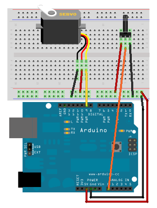
This is what the circuit will look like:
Notice that the orange wire goes to the "Analog In" pin 0 (A0).
The code is available under the File menu. Choose: Examples | Servo | Knob. This is what the code looks like (with modified comments):
// Controlling a servo position using a potentiometer (variable resistor)
// by Michal Rinott <http://people.interaction-ivrea.it/m.rinott>

#include <Servo.h>

Servo myservo;  // create servo object to control a servo

int potpin = 0;  // analog pin used to connect the potentiometer
int val;    // variable to read the value from the analog pin

void setup()
{
  myservo.attach(9);  // attaches the servo on pin 9 to the servo object
}

void loop()
{
  // reads the value of the potentiometer (value between 0 and 1023)
  val = analogRead(potpin);

  // scale it to use it with the servo (value between 0 and 180)
  val = map(val, 0, 1023, 0, 179);

  // sets the servo position according to the scaled value
  myservo.write(val);

  // waits for the servo to get there
  delay(15);
}
Remember that the values input from the pot are going to be between 0 and 1023 and that the servo uses values between 0 and 180 to control its arm position. Based on this, we can not use the values directly from the pot to drive the servo. We first use the map function to convert the pot value to a value between 0 and 180:
val = map(val, 0, 1023, 0, 179);
Try this circuit out! You should find that by moving the pot dial, the servo moves.
Accelerometers have become an important input in many of today's high tech devices, and they can be easy to use. This section provides circuit and code to move the servo with an accelerometer/tilt sensor designed for LEGO Mindstorms NXT. Application idea: control the tilt on a tilt maze using an accelerometer.
This is what the circuit will look like:
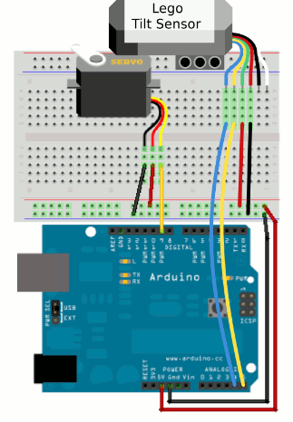
The individual pins (or colors) of the Lego Accelerometer cable can be summarized with the following details:
You may be wondering what I2C clock and data are. I2C is a standardized way of communicating to other and multiple devices that are not Arduino specific. I2C relies on two wires: clock (SCL) and data (SDA). The awesome part of I2C is that you will have a broader choice of devices when working on your project.
The following diagram is meant to represent the parts of I2C communication: the two wires (SCL and SDA), the Arduino attached as the master, the tilt sensor attached as the slave, and optional other devices attached as additional slaves.
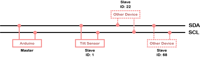
You will notice that each slave has an ID. This is so that the master can communicate with one particular slave. If you are getting mixed up with all this master and slave talk, just remember the important details: I2C allows communication to happen and the Arduino needs to know the ID of the device with which to communicate.
The communication that occurs between the Arduino and the accelerometer can be summarized by the following diagram:
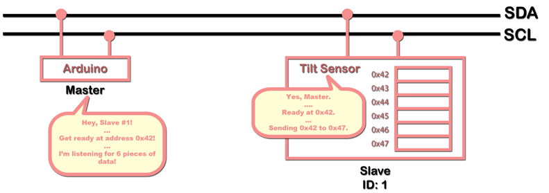
Notice that the master needs to first say who he is talking talking to (Slave #1), then he needs to specify another address (0x42). Then, he says that he will wait for 6 pieces (bytes) of data.
Notice that the Tilt Sensor in the diagram above has some numbers with boxes beside them. These represent register addresses and corresponding registers. You do not need to understand what a register is, you just need to understand that the register will contain specific information as described in the table below (taken from the accelerometer's product description page, http://www.hitechnic.com/cgi-bin/commerce.cgi?preadd=action&key=NAC1040):
| Address | Type | Contents |
|---|---|---|
| 0x42 | byte | X axis upper 8 bits |
| 0x43 | byte | Y axis upper 8 bits |
| 0x44 | byte | Z axis upper 8 bits |
| 0x45 | byte | X axis lower 2 bits |
| 0x46 | byte | Y axis lower 2 bits |
| 0x47 | byte | Z axis lower 2 bits |
Notice that the addresses have a funny 0x in front of the number. This means that the number is in "hexadecimal"-a number system that goes up to 16 (0 to 9 and then A to F).
We will now look at the code which goes along with the communication summarized in the above diagram.
You can use the following code to drive the servo based on the accelerometer's x-axis movement:
#include <Wire.h>
#include <Servo.h>

Servo myservo;
int pos = 90;


void setup()
{
  myservo.attach(9);
  Wire.begin();
  Serial.begin(9600);
}

void loop()
{
  //Variables for Accelerometer readings
  byte x_up;
  byte y_up;
  byte z_up;
  byte x_low;
  byte y_low;
  byte z_low;
  //static means these variables will keep their values
  //without static they would be reset to 0 every time loop
  //restarts
  static float cur, prev, prev2, prev3, avg;

  //Put in a request for information from the sensor
  Wire.beginTransmission(1);  // 1 is the address of the accelerometer
  Wire.write(0x42);           // 0X42 is the location of x_up
  Wire.endTransmission();

  //Receive the information
  Wire.requestFrom(1, 6);

  //wait for all bytes to be available or "timeout"
  int i = 0;
  const int timeout = 10000;
  while(Wire.available() < 6 && i < timeout)
  {
    i++;
  }

  // if we did not "timeout"
  if (i != timeout)
  {
    //Accelerometer readings are 10-bit values sent as unsigned bytes.
    //First three bytes are 8 highest order bits
    x_up = Wire.read();
    y_up = Wire.read();
    z_up = Wire.read();

    //Last three bytes are 2 lowest order bits
    x_low = Wire.read();
    y_low = Wire.read();
    z_low = Wire.read();
  }

  //Combine high and low bytes
  //(this is a bit tricky - it uses coercion to int)
  int x,y,z;
  x = x_up > 127 ? ((x_up&0xFF) - 256) * 4 + x_low: x_up * 4 + x_low;
  y = y_up > 127 ? ((y_up&0xFF) - 256) * 4 + y_low: y_up * 4 + y_low;
  z = z_up > 127 ? ((z_up&0xFF) - 256) * 4 + z_low: z_up * 4 + z_low;

  //(Optional) Print values to the serial monitor.
  Serial.print("x: ");
  Serial.print(x);
  Serial.print("\ty: ");
  Serial.print(y);
  Serial.print("\tz: ");
  Serial.println(z);

  //Smoothing - blend last four readings
  prev3 = prev2;
  prev2 = prev;
  prev = cur;
  cur = x;
  avg = (prev+prev2+prev3+cur)/4.0;

  //Limit the range of values - ignore values outside -200 to 200
  //(actual range is -255 to 255 where 200 is 1 gravity)
  avg = constrain(avg, -200, 200);

  //Map to a servo-friendly range
  int degree = map(avg,-200, 200, 0, 180);

  //Write value to servo
  myservo.write(degree);
}
From the communication end of things, the important lines of code are:
From the data acquisition end of things, the important lines of code are:
Try this circuit out! You should find that by moving the accelerometer up and down (as shown in the diagram below) the servo moves.
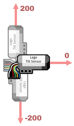
The movement demonstrated in the diagram above is for the x-axis and is in the range of approximately 200 to -200. You can also drive the servo based on the y-axis, which is more of a "roll" of the device from side to side (the code will have to be appropriately changed). At this time, the z-axis data is returned with noise.
It takes a lot of code to get a simple reading from the Accelerometer. It would probably be a good idea to move the code into a library that you can include in any program you want with just a couple of lines, like the Servo library. We have started a library for you to work with. Instructions on using can be found below:
/*
  HTAccel Print
  Prints off X values read from a HiTechnic Lego accelerometer
  using the HTAccel library provided in the CS207 notes.

  Created Oct. 18 2012 by Alex Clarke
 */

#include <HTAccel.h>
#include <Wire.h>

void setup() {
  Wire.begin();
  Serial.begin(9600);
}

void loop() {
  int reading = readHTAccel_X();
  Serial.println(reading);
}