You will know you got this sketch right if the motor spins at
two
different speeds. Your lab instructor will supply a visual aid to help
you see your motor spinning.
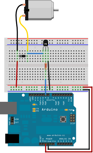
Build Notes:
|
|
The code for the motor sketch:
    /*
 * Arduino Experimentation Kit Example Code
 * CIRC-03 .: Spin Motor Spin :. (Transistor and Motor)
 *
 * Modified Oct 11 2011 by Alex Clarke.
 */

// constants
const int motorPin = 9;

// prototypes for user defined functions
void motorOnThenOff();
void motorTwoSpeed();

void setup()
{
  pinMode(motorPin, OUTPUT);
}

void loop()
{
  //motorOnThenOff();
  motorTwoSpeed();
}

/*
 * motorOnThenOff() - turns motor on then off
 * Notice we use digital writes,
 * just like with LEDs.
 */
void motorOnThenOff()
{
  const int onTime = 2500; //the number of milliseconds for the motor to turn on for
  const int offTime = 1000; //the number of milliseconds for the motor to turn off for

  digitalWrite(motorPin, HIGH); // turns the motor On
  delay(onTime); // waits for onTime milliseconds
  digitalWrite(motorPin, LOW); // turns the motor Off
  delay(offTime); // waits for offTime milliseconds
}

/*
 * motorTwoSpeed() - turns motor on then off but uses speed values as well
 * Notice we use analog writes to set motor speeds,
 * just like with LED brightness.
 */
void motorTwoSpeed()
{
  const int onSpeed = 200; // a number between 0 (stopped) and 255 (full speed)
  const int onTime = 1000; //the number of milliseconds for the motor to turn on for

  const int offSpeed = 27; // a number between 0 (stopped) and 255 (full speed)
  const int offTime = 2500; //the number of milliseconds for the motor to turn off for

  analogWrite(motorPin, onSpeed); // turns the motor
  delay(onTime); // waits for onTime milliseconds
  analogWrite(motorPin, offSpeed); // turns the motor Off
  delay(offTime); // waits for offTime milliseconds
}
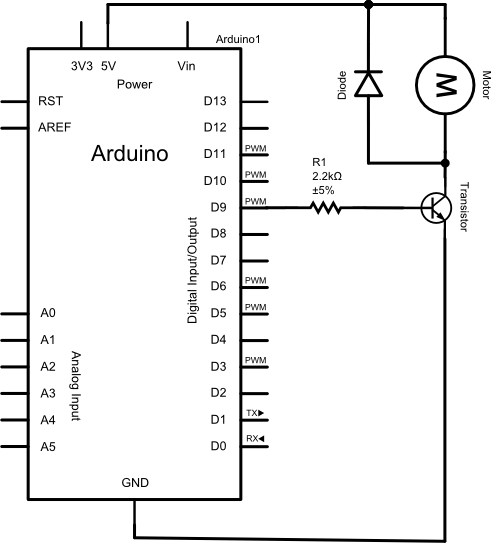
So far we've been able to do what we want with the Arduino's input and output pins. They're fine for controlling low current devices. Some devices, like electric motors, require more power. If you try to drive these devices with the Arduino's pins, the devices may not work, and the Arduino's pins will soon break. To use high current devices you need the ability to control the +5V supply or an external power supply. One component in your kit that allows you to do this is the transistor. Transistors are solid state devices (no moving parts) that use a small current to control a much larger current.
Your ARDX kit comes with a toy electric motor similar to the ones used in RC cars:
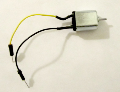
Electric motors move because of magnetism. They contain permanent magnets surrounding a freely spinning electromagnet core. An electromagnet is a piece of iron with wire wound around it. Brushes connect this wire to the two wires sticking out of the motor. When current passes through the wire the core becomes magnetic. Because the core can spin freely it will move so it aligns with the magnets surrounding it. There is a mechanism that switches the current's direction so that the electromagnet never quite lines up with the permanent magnets causing the motor to keep spinning as long as there's a strong current.
Electromagnets can be used to generate power. This is a property of coils of wire, or inductors. Because of this you have to take precautions when you use them to prevent doing damage to sensitive components in the circuit. When you try to turn off an inductor it turns its magnetic field back into electricity flowing in the same direction as the previous current. This happens very quickly and the voltage can be very high - up to 10 times the source voltage. If you don't do something to dissipate the energy safely it can cause sparks to fly between wires, or it can cause surges of power to pass through electrical components like the transistor in this week's circuit or your Arduino's pins. Diodes are used in a special configuration to dissipate these power surges.
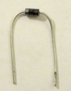
As you have learned, diodes only allow electricity to pass through them in one direction. The positive end is the anode and the negative end is the cathode. Diodes are made of semi-conductors, usually silicon. There are two "flavors" or dopings of silicon inside, a p-type (positive) doping for the anode and an n-type (negative) for the cathode. The side by side arrangement of differently doped semiconductors only allows electricity to flow in one direction.
This property is being exploited in this circuit to protect the transistor. A diode placed parallel to an inductor and backward to the normal flow of electricity in a circuit is called a flyback diode. When current is flowing through the motor and the switching transistor, the diode does nothing because it is backward, or reverse biased. When the the transistor stops flow to ground, the inductor produces a strong forward voltage. The diode connects the two ends of the inductor and forms a low resistance loop - a flyback loop. The surge will go round and round this loop until it dissipates.
You can see a flyback diode in action if you replace the regular diode with an LED. Don't do this for too long though or you may cause damage. Flyback diodes have very low forward voltage, usually less than 1 volt. LEDs typically have a forward voltage of 1.7 volts. Flyback diodes must have a reverse breakdown voltage that can handle the motor's power supply.
Transistors are awesome multipurpose components. Their invention enabled the modern era of electronics. Your kit contains two transistors. Be careful not to confuse them with your kit's temperature sensor. If you look carefully at the flat side you should see an inscription like the one pictured below. If you see TMP on it, then you have the wrong part.
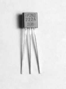
The transistors in your kit are NPN transistors. NPN stands for negative positive negative which is their internal silicone structure. They are a bit like two diodes that share an anode. When you apply a charge to the base (the middle of the NPN sandwich), it allows current to flow across the transistor. This current can only flow in one direction. The positive side of this flow is the collector and the negative side is the emitter. A small amount of current applied to the base can allow very large amounts of current to flow from the emitter to the collector.
Different transistors have different pin arrangements. You will need to find what pin arrangement corresponds to your specific transistor. Notice the text on the flat side of the transistor? ;-)
The other transistor-like component in your ARDX kit is actually a complicated integrated circuit (IC) that can sense temperature. If you put it in a 5V circuit it will provide a voltage based reading that is related to its temperature. BE CAREFUL TO PLUG TEMPERATURE SENSORS IN CORRECTLY! In rare instances, plugging a temperature sensor in wrong can lead to burns!
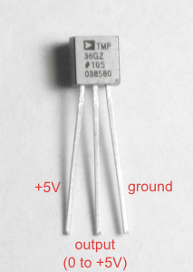
You need to know some properties of the sensor (datasheet here) to convert its output to a temperature in degrees:
Although this week's circuit seems complex, things quickly get much harder if you want to add even basic features to it. Controlling a motor so it can spin in two directions is far more complicated than this week's circuit. Driving bigger motors requires a larger power supply than the 5V USB cable or your kit's battery pack and a special transitor arrangement. Motor noise can ruin other parts of your circuit. Teaching you how to solve all these things is far beyond this introductory lab. Also, nobody should have to build EVERYTHING from scratch or we would be starting with building an Arduino from sand. To help you with more complex issues you can buy pre-built solutions. Some great ones, called Arduino Shields are built to be plugged directly into your Arduino Uno.
Arduino shields work a little bit like game cartridges. They use the (sort of) standard layout of your Arduino's pins to allow you to plug in different circuits. This makes it easy to move your Arduino from project to project. There are many shields available. The in-person version of this lab uses the Danger Shield a few times, which is mostly just for fun and learning. Most shields make a duplicate set of Arudino headers available to you so you can add your own circuits to unused pins. Some are even designed to be stacked one on top of the other so you can mix and match features that meet your project's needs.
Here's a list of links to some useful shields:
Edmonton based Solarbotics stock a wide selection of Arduino Shields and offer 1 to 2 day delivery to Regina for items they have in stock.
Because the Arduino world is a bit of a DIY (Do It Yourself) kind of place, many shields are shipped as a printed circuit board and loose parts. You get to solder them together yourself. The Danger Shield came that way. It can be great fun to learn to solder, and it is very rewarding when the finished product works.
If you look at this week's sample code, you will notice that
loop() has almost no code in it. All the work is being done by user
written functions. You can use comments to easily change whether the motor is
dual-speed or simply on-off.
Functions are really nothing new to you. You defined the behaviour of a function every time you wrote a
loop() or setup(). You have been using or calling functions to do almost everything you
have done with your Arduino. Some functions, like digitalWrite() and
tone(), are commands that perform an action that is
controlled by arguments. These are
called void functions. Others
functions, like analogRead() and map(), provide you with
information that your can use later in your sketch. These are called value returning functions. Both types of
functions are meant to hide the messy details of a complicated task and give it
a useful name.
User written functions are often declared before they are actually used/called. This forward declaration is also known as a function prototype. The general syntax of a function prototype is:
returnDataType functionName(ParameterList);
int, float, or char
and so on.
If the function is a command that does not return any value, we use the
word void
for the return data type.returnDataType functionName(ParameterList)The first line is a restatement of the prototype without the semicolon at the end. The rest of the function is a sequence of commands. If your function has a non void return type, your function must return a value. The function ends when a return statement is reached, even if there are more lines of code that follow.
{
Statement
.
.
.
return data; //only if returnDataType is not void!
}
motorOnThenOff():void motorOnThenOff();
void loop()
{
 motorOnThenOff();
}
void motorOnThenOff(){
 const int onTime = 2500; //the number of milliseconds for the motor to turn on for
 const int offTime = 1000; //the number of milliseconds for the motor to turn off for

 digitalWrite(motorPin, HIGH); // turns the motor On
 delay(onTime); // waits for onTime milliseconds
 digitalWrite(motorPin, LOW); // turns the motor Off
 delay(offTime); // waits for offTime milliseconds
}
If you want to be able to control the motor's on and off times then you would change the function and its call like this:
Prototype:void motorOnThenOff(int onTime, int offTime);
void loop()
{
  motorOnThenOff(2500, 2500); //Change the arguments to change on and off times
}
void motorOnThenOff(int onTime, int offTime){
 const int onTime = 2500; //the number of milliseconds for the motor to turn on for
 const int offTime = 1000; //the number of milliseconds for the motor to turn off for

  digitalWrite(motorPin, HIGH); // turns the motor On
  delay(onTime); // waits for onTime milliseconds
  digitalWrite(motorPin, LOW); // turns the motor Off
  delay(offTime); // waits for offTime milliseconds
}
/*
 * Analog to Volts Function Demo
 * Created Oct 2011 by Alex Clarke.
 */

// Function Prototype
float AnalogToVolts(int reading);

void setup()
{
  Serial.begin(9600);
}

void loop()
{
  int reading;
  float volts;
  reading = analogRead(A0);

  volts = AnalogToVolts(reading);  //Function call

  Serial.println(volts);
}

// Function Definition
float AnalogToVolts(int reading)
{
  float volts;
  volts = reading/1023.0 * 5.0;  //Perform conversion
  return volts; //Return result
}
AnalogToVolts function, but:
CelsiusToFahrenheit() or CtoF()float called Celsius rather than an int called
readingfloat representing Fahrenheit, rather than a float representing volts.
According to Wikipedia the formula to convert Celsius to Fahrenheit is:During the lab:
C: 26.25	F: 79.24	 Motor ON
C: 26.25	F: 79.24	 Motor ON
C: 25.76	F: 78.36	 Motor ON
C: 25.27	F: 77.48	 Motor ON
C: 25.27	F: 77.48	 Motor ON
C: 24.78	F: 76.60	 Motor OFF
C: 24.78	F: 76.60	 Motor OFF
C: 24.29	F: 75.72	 Motor OFF
C: 24.29	F: 75.72	 Motor OFF
Motor ON/OFF messages will also be helpful to your lab instructor during marking, but are optional.
In URCourses before next lab (6 marks):