Take a few moments to build this circuit and install the sketch code. You will know you got things
right if you hear weird noise coming from the piezo that changes and
sounds "video-gamey" as you twist the potentiometer. The LED will be
off most of the time but may flicker occasionally. If you have an
Arduino Mega the tone will be pure and the LED will change brightness
as you turn the potentiometer.
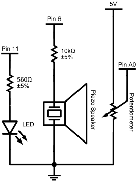
This circuit isn't too complicated. Pin A0 should be connected to
the middle pin of the potentiometer. For everything else come up with
your own interpretation of the schematic below.
  /*
  Playing with pots.
  Written 23 Aug 2011 by Alex Clarke
  */

 //constants for this sketch
 const int ledPin = 11;
 const int piezoPin = 6;
 const int potPin = A0;

 // variables for this sketch
 int pot_value;
 int frequency;

 void setup()
 {
   pinMode(ledPin, OUTPUT);
   pinMode(piezoPin, OUTPUT);
 }


 void loop()
 {
   //read voltage from the potentiometer
   pot_value = analogRead(potPin);

   //Set the LED to brightness pot_value
   analogWrite(ledPin, pot_value);

   //Play the sound represented by frequency pot_value
   tone(piezoPin, pot_value);
 }
The Arduino's six analog inputs are able to sense different voltage levels and convert them to numbers you can use in your sketch. Some input devices provide voltages you can use directly. Others require creative use of Ohm's law and the concept of voltage division to use with your Arduino. Some devices provide analog values based on time rather than voltage and require additions to the Arduino language to use. This lab we will use voltage division and a couple related devices. Next lab you will explore some of the other types.
The lab demo will show how to use a multimeter like this one to help measure the properties of your circuits:
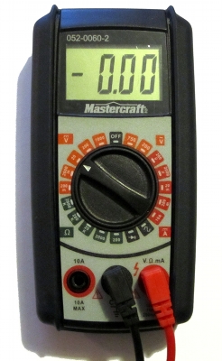
and you'll see how to use Ohms Law and your Arduino's analog input readings to confirm these measurements.
You should recall from class that Ohm's law relates Voltage, Current and Resistance like this:
Let:
V be voltage in Volts
I be current in Amps
R be resistance in Ohms.
Then:
V = I R
You should also have been shown the following diagram that helps you know how to rearrange Ohm's Law to solve for different parts of the equation:

You will be directly applying this law in this lab.
Voltage division is an effect seen in simple series circuits with
multiple resistive components. Between each component of the
circuit you can measure a different voltage that is related to the
total resistances before and after that point in the circuit.
A series circuit in a stable state has one current value that is
constant from end to end. The value of this current can be determined
with Ohm's law, using the total resistance of all components in the
circuit.
Over the circuit the voltage will drop from high to low in the
direction of the current. On your Arduino this means it will drop from
+5V to 0V. The voltage drops as it passes through resistive components in the circuit. The
amount the voltage drops across each of these components can be calculated using
Ohm's law. We then can calculate a voltage value for the wires between
components in the circuit.
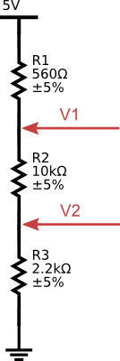
Let's combine these two concepts to calculate the voltages between
the resistors in the following circuit. You may assemble the circuit
and verify the calculations with your multimeter if you wish.
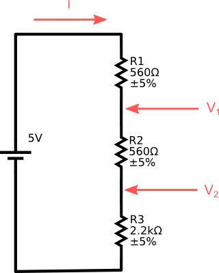
First, calculate the current for this circuit:
I = V / R
= 5V / (560Ω + 560Ω + 2200Ω)
= 5V / 3320Ω
≈ 0.001506A
≈ 1.506mA
You can confirm this with your multimeter:
VR1 = I R1
≈ 0.001506A × 560Ω
≈ 0.8434V
VR2 is the same as VR1
VR3 = I R3
≈ 0.001506A × 2200Ω
≈ 3.313V
Vin ≈ 0.8434V + 0.8434V + 3.313V ≈ 5V
At point V1:
V1 ≈ 0.8434V + 3.313V ≈ 4.156V
At point V2:
V2 ≈ 3.313V
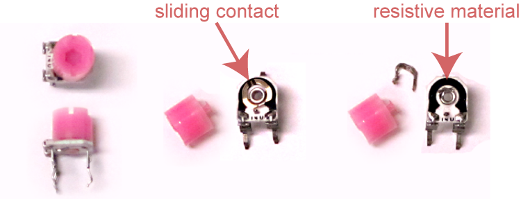
Potentiometers are the component behind most knobs that you see on electronic devices. They work by the principle of voltage division to adjust output voltage between two reference levels.
Inside they have a length of resistive material, often graphite or a carbon/plastic mixture, that is
connected to terminal wires at either end. A sliding contact connected to a third terminal is
moved back and forth
across the resistive material, usually with some kind of knob or
slider. The the resistance between the contact
and the two end terminals is related to the distance to the terminals — longer is more
resistive and shorter is less.
The resistive material in most potentiometers stays the same along its length. Its resistance is directly, or linearly, related to length. In other potentiometers, the resistive material is tapered or changes properties across its length. This type is used in audio applications and is usually more expensive. The amount of resistance in this type is usually logarithmic - it increases with a curve that matches human sound perception.
Some potentiometers are meant to be used often. They are rugged and can be fitted with large knobs. Others are small and are meant to be hidden away. These are called trimpots, and are used by experts to tune a complex circuit. They are not meant to be used often and will wear out if twisted frequently.
The small blue potentiometer in your ARDX kit is a linear trimpot.
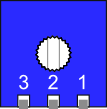
The pins labeled 1 and 3 are should be connected to two different
voltage levels. Pin 2, the middle pin, will have a voltage between the
levels on pins 1 and 3. Turning the knob counterclockwise will adjust
pin 2's voltage toward that of pin 1, and clockwise adjusts it toward
that of pin 3. If that seems confusing, then try rotating your trimpot
so that the pins are away from you. Then it should make more sense.
If you use your potentiometer to measure the Ohms between pins 1 and 3 the value should remain constant. If you measure from pin 1 or pin 3 to pin 2 the value will change as you rotate the knob. In an ideal potentiometer the total of the two should add up to the number from pin 1 to pin 3. In the real world, the total is always a little smaller because the contact is a conductor with a measurable width.
To use a potentiometer with your Arduino you usually connect:
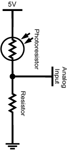
Photoresistors are resistors that vary their resistance when exposed to light. They are less resistive under bright light than under dim light or in darkness. To use a photoresistor with your Arduino you must put it in series with a resistor to perform voltage division. A typical photoresistor sensor circuit would usually look like this:
The range of values you read at the analog input depend on the resistance properties of the photoresistor and the voltage division resistor you select. Once you know these, you should be able to calculate the range using Ohm's law.
There are two three pin components in your ARDX kit. One is a transistor. The other, pictured below, says TMP 36GZ on the flat side of its case and is actually a complicated integrated circuit (IC) that can sense temperature. If you put it in a 5V circuit it will provide a voltage based reading that is related to its temperature.
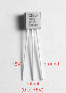
You need to know some properties of the sensor (datasheet here) to convert its output to a temperature in degrees:
It is possible to use a pair of digital inputs on your Arduino to detect if someone is near to or touching a metal plate. If you use the right combination of resistors, metal and insulators you can make a pressure sensor. This page on capacitive sensing at arduino.cc explains the theory behind the technique and gives a tutorial on how to build and use such a sensor. You will not have to build one in lab. Instead your lab instructor will provide one on an Arduino shield called the Danger Shield.
The ability to read a touch sensor is not built into the Arduino or its IDE. Instead you need to install and include a library - the Capacitive Sense library - to make it work. Please refer to the section on installing libraries to learn how to install the Capacitive Sense library.
tone(pin, frequency);
The tone() command causes a note to begin to play on a
pin at the specified frequency. The note will keep on playing while
your program runs until another tone command is sent with a different
frequency, or a noTone() command is sent.
There is a second form of tone() command that will stop automatically:
tone(pin, frequency, milliseconds);
As with the simple tone() command, your program will keep running while the note plays. If you want to wait for the sound to end before continuing with the program, you must use a delay() command of the same length as the tone. If you want silence between consecutive tones, you will need to use a longer delay.
Note: The tone() command has a nasty gotcha! It uses the PWM timers for pins 3 and 11 to make the note play automatically. Trying to use analogWrite() on those pins while you use the tone() command will cause strange things to happen. The first build sketch uses pin 11 to send analog writes to an LED which is causing interference. Change the sketch so it uses a different PWM pin. Enjoy the purer tones.Sometimes it's nice to be able to see what's going on inside your sketch. You can print values from your Arduino program to the computer and view them with the serial monitor in the Arduino software.
To begin sending messages to your computer you use the Serial.begin() command. You should use it in the setup() procedure. Try adding this to your setup():
Serial.begin(9600); // 9600 baud is the default serial communication speed
To send a message to the computer you use the Serial.print() or Serial.println() commands. They can print one variable or constant. They can also print a text message. Try adding this to your loop() just after the analogRead() command:
    Serial.print("I just read: "); //Print some text
    Serial.println(pot_value);     //Print pot_value and go to next line
    //delay(500);  //You may want to slow down the messages so you can keep up
To see the resulting messages press the Serial Monitor button —  — in your Arduino software. A window will pop up, your sketch
will restart and text should appear. There's a menu in the lower right
corner with a list of alternate speeds you can use with the Serial.begin() command.
— in your Arduino software. A window will pop up, your sketch
will restart and text should appear. There's a menu in the lower right
corner with a list of alternate speeds you can use with the Serial.begin() command.
The analogRead() function returns an integer value between 0 and 1023 where 0 represents 0V and 1023 represents +5V. This is nice, but not helpful. You need to do some work to tell your Arduino how you want to respond to these values. Here are two basic strategies you can use to interpret analog input.
The map() function changes input values from one integer range to another. Here's a sample function call:
result = map( input, fromLow, fromHigh, toLow, toHigh);
For example, if you use raw values from the analog port with the tone() function, the results cover several octaves and includes frequencies lower than you can hear. The tone() function can't even reproduce the lowest tones properly. That's why this sketch sounds weird in some positions even after fixing the PWM pin conflict. The result is hard to control. You might have more control if you map analog values to one octave. The official reference note for modern music is A440 or 440Hz. One octave higher than that is A880 or 880Hz. We can map from (0,1023) to (440,880) to get exactly one octave. Change your tone playing code from this:
  //Play the sound represented by frequency pot_value
  tone(piezoPin, pot_value);
to this:
  //Map pot_value to a usable frequency
  int freq = map(pot_value, 0, 1023, 440, 880);
  tone(piezoPin, freq);
Note: the results of the map() function are integers or whole numbers. If you try to use map() to convert analog readings to volts, like this:
float volts = map(pot_value, 0, 1023, 0, 5);then you will only get the numbers 0, 1, 2, 3 ,4 or 5. If you want more precise results you need to use the float type which allows decimal places. You could then calculate voltage like this:
float volts = 5.0 * pot_value/1023.0;
  //Set the LED to brightness pot_value
  analogWrite(ledPin, pot_value);
with this code:
  //Set a LED on/off threshold where the potentiometer passes the mid-point
  if (pot_value < 512)
  {
    digitalWrite(ledPin, LOW);
  }
  else
  {
    digitalWrite(ledPin, HIGH);
  }
What this does is check to see if the voltage is less than halfway between 0V and +5V. That is 1023÷2 or 511.5. When the potentiometer is exactly in the middle it should be near this value. If it is past it, the LED will turn on. If it is below it the LED will turn off.
You can also use a pair of thresholds to check if an input value lies inside a certain range. Change the above code as follows to light the LED when you are close to the midpoint on the pot:
  //Turn the LED on only if it is near the the mid-point
  if (pot_value < 500 || pot_value > 524)
  {
    digitalWrite(ledPin, LOW);
  }
  else
  {
    analogWrite(ledPin, HIGH);
  }
It is better to use a range check like this than to check to see if your potentiometer is at an exact value using the == operator because it is very difficult to accurately position a potentiometer.
Now that you've mastered voltage division, use it to make your photo resistor control a night light.
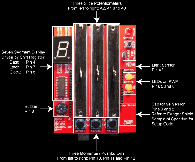
When you have demonstrated the Night Light sketch, your lab instructor will give you a Danger Shield. It is made and sold by SparkFun electronics. You will be using it a various times this semester because it includes ready to use sensors and outputs.
The Danger Shield has many of the same components found in your kit pre-wired to certain pins. Included are a couple simple LEDs and a photo resistor based sensor which is set up a lot like the one you used for your night light. Examine the photo below to see which pins they are on and adapt your Night Light sketch to the Danger Shield.
Note: the Danger Shield may use a different resistor than you, and it may be set up backward to how you set it up. You might want to recalibrate your threshold.
Adapt the First Build sketch so that, as you turn the potentiometer, the piezo speaker only plays notes in the 12 tone (chromatic) equal tempered scale. Because this scale can be easily calculated you may use math to make the code compact, or you may use arrays to make it fast.
The frequencies for an equal tempered chromatic scale from C4 to C5 are:
| Note | C4 | C♯4/D♭4 | D4 | D♯4/E♭4 | E4 | F4 | F♯4/G♭4 | G4 | G♯4/A♭4 | A4 | A♯4/B♭4 | B4 | C5 |
|---|---|---|---|---|---|---|---|---|---|---|---|---|---|
| Freq. | 261.63 | 277.18 | 293.67 | 311.13 | 329.63 | 349.23 | 369.99 | 391.00 | 415.30 | 440.00 | 466.16 | 493.88 | 523.25 |
Beginner
Use your if/else skills to select the correct note to play.
Intermediate
Put the frequency values in an array, then use the map() function to calculate
what index to use to look up frequencies in the array.
Advanced
Use map() or some other calculation to determine the note number in a scale.
Use this value as n in the the formula discussed in this Wikipedia article on Piano key frequencies.